R&D News, Technical Reviews and Mini Features
Website: http://www.cimwareukandusa.com
Email: cimware@cimwareukandusa.com

R&D News, Technical Reviews and Mini Features
Website: http://www.cimwareukandusa.com
Email: cimware@cimwareukandusa.com
R&D News, Technical Reviews and Mini Features
As a general idea let us suggest that as you
read the article simultaneously open and view the figure, or image in
the browser in a separate window by choosing "New Window with this
Link..." by keeping the mouse button pressed down immediately
after you have clicked on the hyperlink on the Macintosh, or by using
the right hand side button on the PC.
NASA
To Showcase Shuttles's NEW "Glass Cockpit" and other
Enhancements
NASA's Space Shuttle fleet soars toward the 21st century with a host of enhancements that make today's Shuttle safer, more capable and less expensive to fly than ever before. Outfitted with the new Multifunction Electronic Display System (MEDS) or "interactive multimedia supported glass cockpit," Shuttle Atlantis is the most modern orbiter in the fleet.
While preparing Atlantis for a December flight, managers will grant a rare peek inside the cockpit to a limited number of media on April 29, 1999. The day will begin with a briefing from Shuttle Upgrades managers and continue with additional media opportunities near other improved Shuttle related hardware like the Shuttle main engines, Super Lightweight Tank, Integrated Vehicle Health Management System and the Checkout and Launch Control System.
During Shuttle Atlantis' last major overhaul, scores of outdated electromechanical cockpit displays like cathode ray tube screens, gauges, and instruments gave way to 11 full-color flat panel screens. Not only does the new system improve crew/orbiter interaction with the easy-to-read, graphic portrayals of key flight indicators like attitude-display and Mach-speed, but it also reduces the high cost of maintaining obsolete systems. MEDS also provides greater backup capability, weighs less and uses less power than the original design.
Shuttle managers removed orbiter Atlantis from flight operations for 10 months as part of a regularly scheduled Orbiter Maintenance Down Period. Atlantis arrived at Boeing's orbiter processing facility in Palmdale, CA, on Nov. 14, 1997, and returned to KSC Sept. 27, 1998 with more than 130 major modifications including enhancements for International Space Station support. Atlantis was made 1,000 pounds lighter than before to increase cargo capacity.
In recent years, upgrades to the Shuttle fleet's main engines have more than quadrupled estimates of their safety and reliability. Weight reductions ranging from lighter astronaut seats to the Super Lightweight Tank have coupled with better performance to increase the Shuttle's cargo capacity by more than 8 tons. Across the fleet, NASA has implemented thousands of major and minor enhancements to the Shuttle's design and decreased the cost of operating the Shuttle by 40 percent during the last seven years.
NASA continues to implement improvements as new technologies like the Integrated Vehicle Health Management System (IVHM) and the Checkout and Launch Control System (CLCS) are developed. IVHM monitors a Shuttle's health while on orbit through a network of hi-tech sensors placed throughout the orbiter. Managers currently depend on a labor intensive process of downloading flight data from Shuttle recorders after landing. Conducting Shuttle checkups with IVHM during a flight gives KSC managers a headstart on upcoming work and leads to quicker turnarounds.
CLCS will replace the dated Launch Processing System currently in use at KSC. CLCS promises modern, commercial off-the-shelf computer systems that will reduce operations and maintenance costs by 50 percent while testing the orbiter in its hangar, monitoring it at the launch pad and controlling the launch countdown.
With Atlantis powered up in the Orbiter Processing Facility, a limited number of reporters will have a brief opportunity to interview Shuttle Commanders, Jim Halsell or Ken Cockrell inside the new glass cockpit. In December, Halsell will command Atlantis' first flight with the new system, a mission to the International Space Station to outfit the station's living quarters. Cockrell will command Atlantis' next flight, another station assembly mission that will attach the U.S. research laboratory Destiny in early 2000.
Shuttle Pilot, Scott Horowitz will be available for interview at the KSC Press Site in front of a full-color display of the Glass Cockpit. Also, Shuttle managers will be available for interview near other improved Shuttle related hardware such as the Shuttle Main Engines, Super Lightweight Tank and the Checkout and Launch Control System.
(This is a carefully selected Research and Development news item based on http://www.ksc.nasa.gov)
KSC,
CONSORTIUM SIGN AGREEMENT TO STUDY ADVANCED METHODS FOR CLEANUP OF
CONTAMINATED GROUNDWATER
Kennedy Space Center and a consortium of other federal agencies are leading the way to develop faster, more economic clean-up methods for numerous contaminated groundwater sites across the country, including an area at Launch Complex 34, Cape Canaveral Air Station.
KSC Director Roy Bridges, Commander of the U.S. Air Force 45th Space Wing General Randall R. Starbuck, and representatives of other participating federal environmental agencies signed a Memorandum of Agreement (MOA) earlier this month formalizing their cooperative efforts to test three innovative solutions in combating groundwater contamination at Launch Complex 34.
The complex is the site of several historic launches as well as the fatal Apollo 1 mission fire. Groundwater at the site became polluted in the1960s because the chemical trichloroethylene was directly discharged into the ground before its toxicity was completely understood. Trichloroethylene was used to clean rocket engine parts.
"All of us represented here today," said Bridges at the signing on April 6, "share the same groundwater clean-up goals, and therefore we also share the associated challenge of remediating one of the more tenacious subsurface contaminates, trichloroethylene, at LC-34."
Trichloroethylene is one of a number of dense non-aqueous phase liquids (DNAPLs) used in industrial procedures that have contaminated groundwater in thousands of sites across the country. The contaminant liquids pose a major long-term threat to drinking water due to their toxicity. The effort to share expertise among agencies in side-by-side comparisons will provide valuable performance and cost data that will result in cost savings efforts to clean-up contaminated sites throughout the country.
"As a kid I believed that NASA embodied the advancement of science in its exploration of space. Now it seems NASA is turning its considerable technical expertise in another direction, 40 or 50 feet down," said Timothy Oppelt, director of the National Risk Management Research Laboratory at the U.S. Environmental Protection Agency, at the signing ceremony.
Cleaning contaminated groundwater areas has traditionally been a matter of "pump and treat," but that can take years and years of effort, leading to huge financial outlays. Proven innovative technologies can provide up to about 60 percent savings in costs, Oppelt said. However, those technologies can only be applied in specific situations, thus the need for testing.
Three 50-by-75 foot test cells have been set up beside the engineering support building at LC-34. Testing of two of the innovative decontamination technologies will begin this summer and testing of the third this fall. The treatments allow for decontamination without removal of the soils. Final results of the study are expected late next year.
Updates on the progress of the study will be posted at the consortium website at www.getf.org/dnaplguest.
In addition to Bridges, Starbuck and Oppelt, other representatives who participated in the MOA signing ceremony were Tom Heenan, assistant manager of environmental management, Savannah River Site, U.S. Department of Energy; Col. James Heald, Vice Commander, Air Force Research Laboratory, U.S. Air Force; Gerald Boyd, acting deputy assistant secretary, Office of Science and Technology, U.S. Department of Energy; James Fiore, acting deputy assistant secretary, Office of Environmental Restoration, Department of Energy; and Walter Kovalick Jr., Ph.D., director, Technology Innovation Office, U.S. Environmental Protection Agency.
(This is a carefully selected Research and Development news item based on http://www.ksc.nasa.gov)
A prototype mobile telephone dropcell has been designed, developed, implemented and tested by an NJIT research team, led by Dr Paul G. Ranky. The overall design (Ranky) of the modular cell incorporates two PLC controlled pneumatic actuators that are capable of automatically dropping and then recovering a mobile telephone as part of an assembly line.
The major challenges of this project were as follows:
Other members of the NJIT R&D team included: Dr. Don Sebastian, Dr. Wayne Chaneski, Mr. Jack Gidney and Ed. Dr. Kevin McDermott. The industrial sponsors of this project were: Lucent Technologies USA, Bell Labs USA and Festo USA. Their kind contributions and support is acknowledged.
FUSE To Check
Fossil Record Of The Universe
A space telescope designed to sort through the chemical muck and star-making stew of the universe will begin scouring for the fossil record of the origins of the universe when it is launched from Cape Canaveral in a few weeks.
The bold examination -- of objects from nearby planets to the extreme outskirts of the cosmos -- is expected to reveal the earliest relics of the Big Bang and provide a detailed picture of the immense galactic structure of the Milky Way. In the end, scientists say the satellite should help them make a huge leap towards understanding how the primordial chemical elements, out of which all life evolved, were created and distributed since the beginning on time.
Among the questions:
On May 20, a team led by The Johns Hopkins University is scheduled to launch a satellite named FUSE (Far Ultraviolet Spectroscopic Explorer) and begin a long-awaited quest to cull answers to some of these vexing questions about the origins of the universe.
"The big questions are these: Do we understand the origins of the universe, and do we understand how galaxies evolve?" said Ken Sembach, a Johns Hopkins scientist working on the project. "Because FUSE can observe wavelengths of light that aren't accessible to other telescopes, we will be able to test models of chemical evolution in unique ways and extrapolate back in time to determine the primordial abundance of an isotope called deuterium, which very well may test the limits of the Big Bang theory."
As one of the first missions in NASA's Origins Program, FUSE extends astronomy's reach much further into the ultraviolet wavelength region, allowing astronomers to test fundamental models of cosmic construction.
The search begins like an archaeological dig around the first minutes of creation. In this case, however, the fossil remnant is not the outline of a leaf or a bone, but evidence of a hydrogen isotope created solely in the Big Bang, called deuterium.
FUSE's instrument will conduct a kind of spectroscopic surgery into the past and present, sampling measures of deuterium and other elements in a variety of places, from the inner recesses of our solar system to the nether-reaches of the Milky Way.
Relying on the telescope's finely-tuned instrument, astronomers will be able to set an accurate benchmark for the amount of deuterium in the Milky Way. With that information, they can then "look back" into time and determine what conditions were like in the infant universe moments after the Big Bang.
Because star creation itself is thought to depend on the regular destruction of deuterium -- as it is essentially chewed up when hydrogen converts to helium -- a map of deuterium abundances in many regions of the Milky Way galaxy will give scientists a better understanding of how chemicals are mixed and distributed and destroyed.
By concentrating on the structure and galactic fountain of the Milky Way, astronomers may end up with a more trusted model of galactic processes in general.
"We will learn a lot about circulation and mixing of chemicals in galaxies and in the star-forming process," said William Blair, a research scientist at Johns Hopkins working on the project. "Are there great galactic fountains constantly cycling material through supernovae explosions and stellar winds, bursting out of the plane of their galaxies, squirting up into haloes, cooling and falling back into the mix? At some level, it must be happening. But we hope to quantify it in a way that has never been done before."
That such an ambitious program arises from one academic department on a small campus in Baltimore might once have seemed preposterous. But besides its commitment to bold astronomy, the FUSE team has made an equally bold commitment to a unique way of doing business, reflecting the desire of one federal agency's goal to do things differently.
In 1995, in an effort to save money, the National Aeronautics and Space Administration (NASA) chose Johns Hopkins to be the first college campus ever to manage an aerospace project of such magnitude. Heading toward launch, the cost of the mission is about one-third what NASA estimated before inviting Johns Hopkins to take over the project.
As another indication of the project's distinctiveness, after launch and for the next three years, FUSE will be controlled and operated by a team of scientists, engineers and students on the first floor of the Bloomberg Center for Physics and Astronomy on the Johns Hopkins campus.
(This is a carefully selected Research and Development news item based on http://www.ksc.nasa.gov)
NASA PLANS AN
EARLY SERVICING MISSION TO HUBBLE SPACE TELESCOPE
NASA will launch a Space Shuttle mission to the Hubble Space Telescope in October 1999 so astronauts can replace portions of the spacecraft's pointing system, which has begun to fail.
Hubble is operating normally and continuing to conduct its scientific observations, but only three of its six gyroscopes -- which allow the telescope to point at stars, planets and other targets -- are working properly. Two have failed and another is acting abnormally. If fewer than three gyroscopes are operating, Hubble cannot continue its science mission and automatically places itself in a protective "safe mode."
"The Hubble Space Telescope is the crown jewel of NASA's space observatories, and we need to do everything within reason to maintain the scientific output of this national treasure," said Dr. Edward Weiler, Associate Administrator for the Office of Space Science, NASA Headquarters, Washington, DC. "We appreciate the rapid response of the Space Shuttle community to this request."
"When Hubble reached the point of having no back-up gyros, our flight rules said we must look at what we term a 'call-up mission' to correct the situation," said Dr. John H. Campbell, the telescope's Project Director at NASA's Goddard Space Flight Center, Greenbelt, MD. "Since we are already involved in preparations for the scheduled third servicing mission next year, we essentially decided to divide the planned mission into two flights and reduce the workload on each."
A team of veteran astronauts had already begun training to install the new instruments and upgrade the telescope's systems. NASA astronauts Steven L. Smith, C. Michael Foale, John M. Grunsfeld and European Space Agency astronaut Claude Nicollier will perform the spacewalks on both servicing missions. Smith is the payload commander for the missions, coordinating the astronauts' space-walking activities. A flight crew for the servicing missions will be selected in the near future.
In addition to replacing all six gyroscopes on the October flight, the crew will replace a guidance sensor and the spacecraft's computer. The new computer will reduce the burden of flight software maintenance and significantly lower costs. A voltage/temperature kit will be installed to protect spacecraft batteries from overcharging and overheating when the spacecraft goes into safe mode. A new transmitter will replace a failed spare currently aboard the spacecraft, and a spare solid state recorder will be installed to allow efficient handling of high- volume data. Both missions will replace telescope insulation that has degraded. The insulation is necessary to control the internal temperature on the Hubble.
The later servicing mission will focus on installing the Advanced Camera for Surveys. With its new imaging capabilities, this camera will be 10 times more powerful than the present Faint Object Camera. New efficient rigid solar arrays will replace the existing solar arrays. Astronauts also will install the Aft- Shroud Cooling System. This new system is designed to carry heat away from the scientific instruments and to allow the instruments to operate better at lower temperatures. The cooling system allows multiple instruments to operate simultaneously, helping the science team maintain the program's high productivity.
In addition, an advanced cooling system will be installed on the Near-Infrared Camera and Multiobject Spectrometer, which became dormant after its solid nitrogen coolant was exhausted in January 1999.
Live shuttle countdown: images taken every 90 seconds, posted onto the wesite indicated below: http://www.ksc.nasa.gov/shuttle/countdown/video/video.html
(This is a carefully selected Research and Development news item based on http://www.ksc.nasa.gov)
STS-96
is a logistics and resupply mission for the International Space
Station.
This will be the first flight to dock to the International Space Station. The SPACEHAB double module will carry internal and resupply cargo for station outfitting.
The Integrated Cargo Carrier (ICC) will carry the Russian cargo crane, known as STRELA, which will be mounted to the exterior of the Russian station segment, the SPACEHAB Oceaneering Space System Box (SHOSS) and a U.S. built crane called the ORU Transfer Device (OTD).
Other payloads on STS-96 are the Student Tracked Atmospheric Research Satellite for Heuristic International Networking Equipment (STARSHINE), the Shuttle Vibration Forces Experiment (SVF) and the Orbiter Integrated Vehicle Health Monitoring - HEDS Technology Demonstration (IVHM HTD).
The STARSHINE satellite consists of an inert, 19-inch hollow sphere covered by 1,000 evenly-distributed, flat, polished mirrors, each 1 inch in diameter. The payload consists of the STARSHINE satellite, integrated with the
Pallet Ejection System (PES), then mounted inside a lidless carrier. The HH equipment consists of one HH, Lightweight Avionics Plate (LAP), then mounted inside a lidless carrier. Additional HH equipment consists of one Hitchhiker Ejection System Electronics (HESE), one 5.0 cubic-foot HH canister, and one Adapter Beam Assembly (ABA). The purpose of the mission is to train international student volunteer observers to visually track this optically reflective spacecraft during morning and evening twilight intervals for several months, calculate its orbit from shared observations, and derive atmospheric density from drag-induced changes in its orbit over time.
The Shuttle Vibration Forces (SVF) Experiment will provide flight measurements of the vibratory forces acting between an aerospace payload and its mounting structure. The force transducers will be incorporated into four custom brackets which will replace the existing brackets used to attach the 5 ft standard canister to the side wall GAS adapter beam. The payload will be activated automatically by the Orbiter Lift-off vibration and will operate for approximately 100 seconds. STS-96 will be the second flight of the SVF experiment.
The purpose of the Orbiter Integrated Vehicle Health Monitoring- HEDS Technology Demonstration (IVHM HTD) is to demonstrate competing modern, off-the-shelf sensing technologies in an operational environment to make informed design decisions for the eventual Orbiter upgrade IVHM. The objective of IVHM is to reduce planned ground processing, streamline problem troubleshooting (unplanned ground processing), enhance visibility into systems operation and improve overall vehicle safety.
Launch: May 20, 1999 9:32a.m. EDT (ESTIMATED). Window 5-10 min.
(This is a carefully selected Research and Development news item based on http://www.ksc.nasa.gov)
SmartDart
for a Smart Force: A Smart Diagnostic, Maintenance and Learning
Support System Implemented in a Voice I/O Controlled, Wearable,
Interactive Multimedia, Computer-based Device for the Automobile (and
other) Industries
by
Professor P. G. Ranky and Professor S. Tricamo
Co-Principal Investigators of the R&D project at NJIT (New Jersey Institute of Technology), USA and project partners including General Motors, Raytheon/Hughes, The National Guard and Interactive Solutions, Inc., USA
Email: ranky@admin.njit.edu
Introduction
SmartDart is a prototype smart diagnostic, maintenance and learning support system implemented in a voice I/O controlled, interactive multimedia, mobile/ wearable computer-based device for the automobile (and other) industries (see photo).
The main features of SmartForce include the following:

(Click on the photo icon to enlarge)
Professors Ranky and Tricamo with the SmartDart computer
About the system architecture
In order to achieve the above listed and other functions, SmartDart is implemented as a small, ruggedized, networked mobile (or desktop) networked computer-based device, that runs on a set of core processes, such as:
SmartDart has a set of core modules linked to a fast knowledge-bus, through which various smart-cards, or modules it can execute various processes. These smart-cards have embed various domain expertise and will be integrated following the object-linking methodology.
SmartDart has an Open System Architecture, meaning, that as the need arises new smart cards can be developed and plugged-in, in a way enhancing its "field expertise". Due to the well integrated, object-linked design architecture, these new modules, or smart cards will automatically integrate with the rest of the system, as well as follow the standard multimedia user-interface design, cutting the learning curve of using a new smart card to minimum.
The typical application scope of SmartDart
In order to explain the typical application scope of our system, let us list some broad application areas, with that of the view of the maintenance technician, or engineer, who's job is to diagnose or fix a problem. In general, SmartDart will answer the following questions and resolve the following problems:
Furthermore, SmartDart can
For further information please contact: Email: ranky@admin.njit.edu
REDHA-CUT:
An Atherectomy Device. A Medical Engineering Micro-robot/ Manipulator
R&D Project
by
Dr. Med. F. Redha, Professors T. Pato (Fachhochschule Bern, Switzerland) and Paul G. Ranky, PhD (Swiss Innovation Prize Winners with the R&D Group, 1995)
REDHA-CUT is a percutaneous transluminal atherectomy device
This new and revolutionary medical device enables the removal of various deposits from the walls of arteries or veins. It is a percutaneous transluminal atherectomy device for medical applications in humans as well as in animals.
It consists of cutting blades that are arranged as an umbrella and which can be opened and closed during the operation by the doctor. The device is introduced into the arteries and advanced through the stenosis. By withdrawing it with open blades deposits in the arteries and veins can be safely cut, retained in the tube end of the device and then removed. The device is then cleaned by the nurse and reentered by the doctor for the next cut. This process is repeated, step-by-step until all deposits are removed safely, without damaging the wall of the artery or vein.
This means that following this patented method the deposit (plaque material) removal is safe and clean since all deposits cut by the device are actually removed from the bloodstream in the tube end of the device. The result of each cutting process is examined by the operating team using fluoroscopy with contrast agent.

The cutting head of the Redha-Cut
(Click on the photo icon to enlarge)
The technical parameters of the device are as follows: the maximum cutting diameter is 4.9 mm, the diameter when closed is 0.265 mm and the length of the plaque retaining tube is 22 mm.
The novel contribution of this patented design is as follows:
This ongoing R&D project was (and is further) sponsored by several European research agencies as well as international institutions and corporations, including EUREKA, FAMOS R&D EU 1227, INTEC, Sherine Med AG, ISBE, CIMware Ltd. UK, University of East London, UK and others.

(Click on the photo icon to enlarge)
(Click on the photo icon to enlarge)
For further information please contact: Email: ranky@admin.njit.edu
Innovative
Laser Technologies, Applications and New Trends
by
Paul G. Ranky, PhD
ADAM, Advanced Design And Manufacturing at www.cimwareukandusa.com, USA
Email: cimware@cimwareukandusa.com
1. Introduction and Overview
LASER, or Light Amplification by Stimulated Emission of Radiation, is a cavity (or resonator) with plane or spherical mirrors at the ends, that is filled with crystal, or glass, or liquid, or dye, or gas, or other materials, the atoms of which are capable of being excited to a semi-stable state by either a light discharge, or an electric discharge ([1]).
The light emitted by an atom, as it falls back to the ground energy state, releases other excited atoms, and as a consequence the light intensity is continually increased as it oscillates back and forth between the mirrors. This process is often referred to as the "stimulated emission". If the cavity is properly designed, it provides continuous tunability without mode hops and with a constant output beam direction. The energy generated by the laser is in or near the optical portion of the electromagnetic spectrum.
If in a laser system only one mirror is made to transmit one to two percent of the light, a beam of monochromatic, coherent radiation (or energy transfer in this context) is emitted through the mirror. If plane mirrors are used, the beam is highly collimated, and if concave mirrors are employed, then the beam emerges from a point source near one end of the cavity.
If the intense, highly directional beam of light, that the laser produces is directed, reflected, or focused upon an object, the laser light energy will partially be absorbed, raising the temperature of the surface and/or the interior of the object. Depending on the intensity of the laser, this can cause an alteration or deformation of the material, including the human body, most importantly the eye and/or the skin.
The above outlined properties of the laser beam can be used for a variety of industrial, commercial, military and research applications. Let us discuss some of these new application possibilities and development trends based on recently demonstrated commercial machines and systems, as well as research.
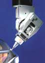
Prima Laser Gun
(Click on the photo icon to enlarge)
2. Industrial Laser Types
Laser applications in industry cover a very wide range of processes, typically by employing various type of lasers, including the following; (note that laser types marked with an asterix * are the most popular in industrial applications):
From a material processing point of view, since the laser beam represents light energy, it is important, that the material to be processed has the capability of absorbing the thermal energy upon impact. Therefore, materials that have high absorption coefficients are efficient thermal converters. As an example, consider, that materials that have high absorption coefficients of 10.6 micro meter wavelength light are efficient thermal converters of the CO2 laser light and represent excellent candidates for laser processing in general.
It is also important, that after the laser light energy is absorbed, it remains concentrated. Therefore materials with low coefficients of thermal conductivity are most likely to be processed successfully by laser, because of their resistance of dissipating energy too rapidly, that could lead to unwanted stresses.
3. Industrial Laser Application Areas
Laser applications in industry and commerce cover a very wide range of processes, including the following (alphabetically sorted list):
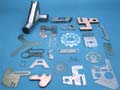
Bystronic laser cut parts
(Click on the photo icon to enlarge)
4. Advanced Manufacturing Applications
Laser processing technology is attractive. Consider, that a leading international automobile manufacturer produces 45,000 parts during nearly 7,366 hours of continuous production over 11 months, all on the same laser system ([2]).
The trend is that in the automotive, aerospace and general manufacturing, precision manufacturing and quality control/ inspection, marking and labeling, welding, and many other industries, companies putting lasers to work because of their continuously increasing and improving speed, accuracy/ repeatability, programmability, and flexibility. Furthermore, as the examples illustrate in this article, several companies offer increasingly better cell control, process planning, programming, networking and automated material handling capabilities with their systems, making them easier to be integrated with the rest of the factory ([3] and [4]).
In order to fully appreciate the development trends, let us discuss a few new solutions and machines/ systems in some detail.
4.1 New ND:YAG laser development
The new Lumonics 4.5 Kwatt Multi wave-Auto laser System is an ND:YAG laser can weld two sheets of 0.8 mm body steel or 1.2 mm aluminium with an overlap joint at more than 6 m/min. It can weld aluminium up to a thickness of 6 mm, and chromium magnesium and stainless steel up to 10 mm. In addition, it can spot weld in steel up to 3 mm diameter ([2]).
Since back-reflection is built into the fiber, it is possible to weld at 90 degrees to the workplace surface, even when reflective metals are being processed. Consequently, the 10 degrees offset to the surface that is normally used to keep reflected energy from damaging the optics isn't necessary. For processes involving high speed cutting, the MultiWave- Auto can cut steel and aluminium at up to 20 m/min.
With the flexible, fiber optic cable delivering the laser beam output, the system is capable of up to four-way time share, meaning that the laser beam can be switched between different workstations in less than 50 msec.
Instead of DC motors, typically used in other laser systems, this new machine uses an AC power supply that increases the lamp life and ensures even wear of the lamp, offering approximately 2,000 hours of lifetime.
Quick release plug and play focus heads offer spot sizes from 0.3 mm to 0.6 mm and a range of other processing aids, including cover glass damage detection, an air knife to prolong the life of the protective cover glass, cutting nozzles, CCTV viewing options and an auto focus cutting head.
As part of the control system, a touch screen panel shows the status of the laser at a glance and offers immediate user access to monitoring, programming and maintenance functions. Each module in the system is designed to carry its own intelligence, including modem-linked remote maintenance, and self-configuration via the embedded network between the modules and the host/ cell control system.
4.2 New developments in engraving and power marking
The beauty of laser marking is that whilst ink marks rub off, laser marks cut into literally any 2D or 3D shapes of automotive metal and plastic components, ceramics, anodized and plated metals, glass, paper, rubber and others, don't. This is even more significant in many industries in which ISO9001/2 part traceability issues, or after-market part identification, or theft prevention are considered to be a must. Furthermore, laser marking is environmentally friendly. There is no ink or any other hazardous material involved.
As an example, the Lumonics LightWriter AMS Laser Marking System can use a range of different Nd:YAG powered lasers. It can meet a wide range of applications, from deep engraving in cast metal parts to low power marking of delicate plastic, ceramic and composite materials and components ([2]).
The system uses an Nd:YAG 75 Watt, 1.06 micron wavelength, multi-purpose laser system, with PC control and the LightWriter AMS software system for programming, running under Windows NT. The programming environment allows the user to use existing TrueType fonts, for accurate lettering, or design specific fonts and company logos, part numbers, or serialization, or bar codes, or 2D matrix codes, graphic images as separate or grouped objects for marking and labeling. (The smallest characters are 0.25 mm in heights, a typical size for marking aircraft wires, and the largest are in the range of 50 mm).
In order to guarantee process matching, users can run identical job files on multiple machines, even at remote locations. Offsets are loaded into each machine to assure consistent results from the same master source program.
System integration is enabled by the PC/Windows NT controller, or by PLC interfacing. The LightWriter AMS software offers digital I/O handshaking as well as a simpler ASCII text interface.
4.3 New developments in multi-axis laser processing
As an example, the Laserdyne 790 BeamDirector Multiaxis Laser Processing System is a five-axis, dual processor PC controlled, high speed, cutting, drilling or welding system for flat or 3D parts used in the automotive industry, such as combustion liners, exhausts, heat shields, flame tubes, nozzle guide vanes and blades, pressed parts and spinnings, and others.
The Lumonics Laserdyne 790 BeamDirector Multiaxis Laser Processing System
(Click on the photo icon to enlarge)
This machine can use either Nd:YAG or CO2 lasers, up to 4 Kwatts, or 3.5 Kwatts, respectively. A new feature in the control system is the automatic focus control (AFC), that allows for high part accuracy and repeatability, making the process more consistent with pressed parts and allowing reduced programming and setup times, since the machine can align itself.
Due to the mechanically rigid construction, the system offers high acceleration and speed by means of Brussels motors, digital motor amplifiers and safe operation by a fully enclosed and purged beam path. The system controller is built of dual PC, Windows NT system, offering simultaneous run/ edit modes, networking, standard G and M code programming, or higher level programming, using the 890 style BeamDirector.
The repeatability of the machine is within 0.02 mm in the X, Y and Z axis, and within 15 arc seconds in the C and D axis. The linear accuracy is impressive too. In the X, Y and Z axis it is within +/-0.01 mm, not to exceed 0.02 mm over full travel and in the C and D axis +/- 15 arc seconds.
4.4 Laser cell material handling and automation trends
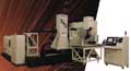
As an example, the Bystronic BYSTAR, high power, high speed, CNC CO2 FMS laser cutting system with automated loading and unloading and sheet storage tower has a modular design concept, that enables expansion and cell integration from a stand-alone machine, to a fully automated FMS system with integrated loading/ unloading and sheet storage.
The latest module, an integrated Sheet Storage Tower, can be mounted to any BYSTAR machine ([4]) with a shuttle table and the BYTRANS load/ unloading system or a loading system with a sheet table and spreader magnets. Comprised of six shelves, the Sheet Storage Tower loads raw material onto the shuttle table via a suction cup loading unit. An automated scissors table is used to fill the tower and to load the laser cutting system. The tower can be run automatically via the 32-bit CNC controller, running the new BYSOFT software, or manually.
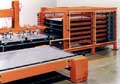
The Bystronic Sheet Storage Tower
(Click on the photo icon to enlarge)
Other new features include the AC drive, that has elevated the machine dynamics to a higher level, by incorporating a powerful high torque at low speed, resulting in high acceleration/ deceleration and positioning speeds. This speed increase translates into significant improvements when cutting intricate parts and contours.
From a cell and FMS control point of view, the new 32-bit CNC controller uses a Windows 95-based programming interface and software system, enabling single part to automatic nesting of cutting plans, as well as through other modules, such as the BYBASE, a database program. Also included is BYTRACE, for processing scanned drawings, BYFRAME for 3D tube constructions, BYPART for the design and programming of flat parts, BYWORK for manual and semi-automatic nesting of parts and BYNEST, for fully automatic nesting of parts.
4.5 Advanced laser cells for improved productivity
As an example, the Rapido 5 split-cabin design laser cell ([5]) offers two large work areas, and is a five axis controlled laser system with an integrated PC/ Windows based cell controller. It offers increased programming and operating performance when cutting 3D prototype or production parts, as well as doubles part cutting productivity by allowing continuous cutting of parts with no lost time for part loading or unloading in production cutting applications.
With the split cabin design, the cantilever-style flying optics laser moves rapidly from one cabin to the next. While the laser is cutting in one cabin, an operator can unload the finished part in the adjacent cabin and load another blank, with no lost time between operations.
Furthermore, the machine offers off-line programming tools, which allows simplified 3D programming directly from CAD IGES files.
The heart of the laser system is a PRC 2,200 Watt laser generator, although the five axis machine is capable of cutting with up to 3,500 Watts of laser power and can be equipped with 5,000 watts of laser power for welding and heat treating applications.
Other new features of this cell include:
Last, but not least, the long Z stroke (600 mm) and the fully accessible working volume are unique characteristics of this machine, which can be integrated with a large range of standard options for presetting, handling and managing each individual application.
5. Health and safety trends
If the laser beam is directed, reflected, or focused upon an object, the light energy will partially be absorbed, raising the temperature of the surface and/or the interior of the object. Depending on the intensity of the laser, this can cause an alteration or deformation of the material. Due to this, the human body is vulnerable to the output of certain lasers, and under certain circumstances, exposure to the laser beam can result in damage to the eye and/or the skin.
Since the cornea, the clear outer front surface of the eye's optics, unlike the skin, does not have an external layer of dead cells to protect it, is almost always more vulnerable to injury than the human skin. The greatest concern of laser exposure is the retinal hazard region of the optical spectrum, approximately 400 nm (one nanometer is one billionth of a meter) violet light to 1400 nm near infrared light, including the entire visible portion of the optical spectrum.
According to the Laser Institute of America ([1]), since light entering the eye from a collimated beam in the retinal hazard region is concentrated by a factor of 100,000 times when it strikes the retina, laser systems have to be designed with utmost care, have to pass national and international safety standard tests, and users/ operators/ researchers and visitors should avoid focusing with their eyes on the laser beam to avoid eye damage caused by direct beam or mirror-like reflection. Due to the light concentration, a visible, 10 milliwatt/cm2 laser beam would result in a 1000 watt/c m2 exposure to the retina, which is more than enough power density to cause damage.
Considering the above, the trend in modern laser processing is to provide full protection and cover on every aspect of the machine, that is specifically designed to prevent the operator to be exposed to the harmful aspects of the laser beam ([1] and [4]).
6. Summary
There is no doubt that the laser system manufacturers are employing increasingly modular design concepts, that ensure that machines, cells and FMSs can be built of modular, so called "plug-and-play" components, as well as that the new, PC-based control systems can be programmed, networked, remotely diagnosed and maintained easier.
On the other hand, this progress is still somewhat behind in comparison to what proven technologies there are available in other industries, notably in control systems engineering, in computing, in communications, in part programming, in CAD/CAM, generally in system integration, in DNC networking, in engineering multimedia, employed as an on-line tutoring and support system, in fault detection and maintenance, and in many other areas.
The very notable trend is that there is a very significant move towards PC-based controllers, that employ relatively user friendly interfaces, more functionality at significantly lower cost, the opportunity of using non-proprietary software tools, such as editors, graphical programming tools, networking solutions and others.
Despite all these positive trends, however, there are still major issues to be resolved, most importantly the lack of fault tolerant operating systems that critical mission control processes desperately need, the lack of intelligent, easy to use machine controllers with interactive multimedia and on-line web/remote support and maintenance systems, and the lack of higher level integration opportunities at significantly lower costs that enable CIM, or as it has evolved into and often referred to: ERM, Enterprise Resource Management systems, in which customer satisfaction (including the operator of the machine as a customer) is the focus.
To summarize, in terms of their communications/ Internet/ intranet-based networking, or remote diagnostics, or unified messaging and server systems, or their engineering multimedia and enterprise-wide resource management software environments laser systems still have many opportunities to advance.
The best advice that could be given to both machine tool and laser system designers and manufacturers is to employ able young teams of engineers, that have grown up in our computing, IT and Internet world, and who have both the process as well as the communications systems expertise and let them integrate existing, well tested, modular, "plug-and-play" computing technologies for the benefit of all parties involved.
References and Hotlinks to Websites of Manufacturers
[1] Laser Institute of America, Orlando, Florida, USA
[2] Lumonics Inc., Product Information, Livonia, Michigan, USA http://www.lumonics.com
[3] Bystronic Inc., Product Information, Hauppauge, Long Island, NY, USA
[4] Cincinnati Inc., Product Information, Cincinnati, OH, USA
[5] Prima US Inc., Product Information, Farmington Hills, Michigan, USA
New
Trends in Flexible, Lean and Agile Manufacturing Cells &
Systems
by
Paul G. Ranky, PhD
ADAM, Advanced Design And Manufacturing at www.cimwareukandusa.com, USA
Email: cimware@cimwareukandusa.com
Introduction and Overview
The view that we do not need manufacturing in the service and information technology society is fundamentally false. The fact of the matter is that if we give up manufacturing and related R&D we might as well give up innovation and design, and consequently give up our potential place in the "knowledge society", the next challenge already being built by our competitors.
The "knowledge society" promises to offer a fairer than ever place for intellectuals who innovate and wish to turn their great ideas into product rapidly and then distribute them over the Internet to a global marketplace without going through the currently very slow and costly marketing, sales and distribution processes.
Obviously even in the knowledge society we won't be able to "physically download" a new machine tool, or robot from the Internet. Nevertheless it is becoming increasingly acceptable to learn about new developments in the cyberspace, and then order such equipment electronically, including new physical hardware that is made to order, new software and various software enhancements or upgrades, or interactive multimedia based local and remote maintenance and training services, and others.
In terms of "New Trends in Flexible, Lean and Agile Manufacturing Cells & Systems" we should recognize that machine tools and other manufacturing resources must become significantly more flexible and programmable. Furthermore manufacturing companies should learn from the major advances in computing science and the IT industry. They must understand better the way they lead mass customization and flexible made-to-order and "shipped overnight manufacturing", and the application of such "wonders" as the Internet and intranets in our new world of globally distributed and networked design, manufacturing, marketing, sales, maintenance and education.
This is a major change to many, as a matter of fact to some it is so new and so frightening that they would prefer to reject it up-front, claiming that this is "crazy" and that it "won't last anyway". We have to go through this process gradually, nevertheless recognizing the fact that there are some very progressive competitors that are less fearful of moving faster towards web-based design and manufacturing with engineering multimedia interfaces and distributed feed-back control at all levels. Obviously if we don't act now, the future is theirs…
So are we planning to be "in" our "out"? And, does this mean that this is the end of the machine tool and the manufacturing industry? Absolutely not, but as we have known it, yes!
Consider that products of the machine tool industry are used in a wide variety of parts and systems, ranging from automotive and aircraft components, ships and railways, medical instruments, electronic assembly systems, a variety of tools, fixtures and clamping devices and even in the case of everyday products, such as coins, the zipper, or the lipstick tube, or the pencil and the pen we use to write.
Besides the diversity of products that the machine tool industry contributes to, there is the major economic factor too, in that it creates significant employment in most countries not just in the industry itself but also in its support and service sectors.
According to many US and international machine tool manufacturers and manufacturing associations, there is no doubt that significant progress is becoming increasingly difficult because ever greater demands are being made by customers, because manufacturing tolerances are narrowing, markets are becoming ever more crowded, competition is fierce, and product quality requirements have never been greater.
This statement is fair considering the traditional aspects of the machine tool and the manufacturing engineering industry, nevertheless in terms of the potential of moving into the design, production and use of flexible, modular, lean and agile machines, cells and systems there are several new, exciting opportunities that should yield great benefits not just for the customers but for the manufacturers too.
In order to support the above outlined need for rapid transition, in this article we'll focus on these new trends, ideas and opportunities with some examples.
New Trends and Exciting Opportunities
Due to the fact that consumer demand is rising and products are expected to meet more, often conflicting requirements, the major trend is that machines, cells and manufacturing systems in general have to achieve [1]
There is no doubt that these are major challenges, and that since the resistance in changing the way we think in the manufacturing industry as well as due to the high cost of design change they will not happen overnight. Nevertheless the commitment to this journey, however outrageous some aspects of it might be at present to the traditional machine tool builder is vital as well as is already evident in several parts of this industry.
Although in most cases still neither fully developed nor integrated, in order to illustrate some of the above listed trends with real-world examples, let us discuss the following products in more detail:
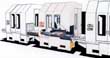
Top loading six-axis robots for cells by Fanuc Robotics North America Inc.
Fanuc's first six &endash; axis top loading robots in North America are available in three models (M-6iT, M-16iT and M-16iTL) that offer a variety of reach and payload capabilities.
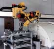
Fanuc Turning cell (the pallet load/ unload operation) http://www.fanuc.com
(Click on the photo icon to enlarge)
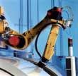
Fanuc Turning cell (the part loading/ unloading robot arm at the machine side of the cell) http://www.fanuc.com
(Click on the photo icon to enlarge)
These overhead robots are designed for flexible and programmable load/unload applications in the machine tool and plastics industries. The modular construction, electric servo-driven robots are engineered for precision, high-speed operation and user-friendly installation.
The robots' six axes of motion, of which one is linear and the rest five axes are rotary, result in a robot capable of serving multiple machines, stations and operations. In addition, the six-axis dexterity enables to re-orient parts between operations and/or service both vertical and horizontal machines.
The rail mount allows top, front and side entry into the machine tool and enables the robot to reach back behind itself to provide a three-dimensional work envelope, as opposed to the two-dimensional work envelopes offered by a traditional gantry robot. The overhead mount allows a full range of motion for secondary operations such as trimming, washing, deburring, palletizing, labeling or packing. It reduces floor space and ceiling height requirements and keeps the front of the machine tool clear.
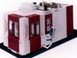
Cincinnati Milacron's Cincron Automated Pallet Cell
Cincinnati Milacron's new single-machine starter cell with automated pallet changer aims the small-to-medium size manufacturer that is willing to enter the world of flexible, cellular manufacturing at an affordable price and then expand.
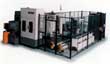
Cincinnati Milacron's new single-machine starter cell http://www.milacron.com
(Click on the photo icon to enlarge)
This cell is built around Cincinnati's Maxim H-500 HMC (Horizontal Machining Center) and is controlled entirely by the HMC's own Acramatic CNC controller ([3]). With the rail guided vehicle shuttling fixtured work from a pool of nine off-line pallets and the automated pallet changer cell design, Cincinnati claims to be able to achieve the spindle in-cut times of 90% and higher possible.
Due to the modular design concept, as production grows, pre-engineered modular components, field-proven in over 140 Milacron cell installations, enable the incremental expansion of the cell into a larger, but still very flexible system.
"Plug-and-play" manufacturing by Cellular Concepts of Detroit
The Linear Pallet Transfer Machine (LPTM) is a new concept for medium-to-high volume machining. It is claimed to be a "transfer line in a box" because of its "plug-and-play" readiness to be linked into a pallet transfer machining system ([4]).
In this custom-scalable, automated system each machine receives automatically a pallet with the fixtured part(s) from the previous adjacent machine, and after processing passes on the pallet to the next machine. Pallets have a max. load capacity of 800lbs (360 kg).
The Linear Pallet Transfer Machine (LPTM) by Cellular Concepts of Detroit (Michigan, USA)
(Click on the photo icon to enlarge)
What makes this "plug-and-play" design interesting is that it greatly reduces the capital cost of a high volume machining line while providing all the flexibility end-users require without the labor cost associated with the machining centre. Formerly such flexibility and productive capacity could only be achieved in a costly custom-designed system.
As George Simon II, Cellular Concepts President claims: "By adding or subtracting machines/ modules, users can increase or decrease production capability and the automated system significantly reduces the high labor cost typically associated with stand-alone machining center solutions."
Each module in this system is controlled by a GEFanuc PC-based cell controller. These PC-based controllers are furthermore used to integrate the system. The simplicity of the control architecture significantly reduces the time to implement, train and maintain and change such systems.
The latest PC-based CNC controllers by G&L Controls
Giddings Lewis's new upgrade NumeriPath 8000 CNC operator station controller is fully compatible with the Microsoft Windows NT ® PC operating system ([5]).
Giddings Lewis's new horizontal machining centre http://www.giddings.com
(Click on the photo icon to enlarge)

Giddings Lewis's new upgrade NumeriPath 8000 CNC operator station controller http://www.giddings.com
(Click on the photo icon to enlarge)
The modular upgrade concept allows existing operator stations to take advantage of the PC based operating system with multitasking and networking capabilities as well as access the vast amount of third party software packages that were not even recognized in the old proprietary CNC world.
Specifically the PC-based CNC controller
The architecture allows the PC to run Windows® applications whilst the machine tool is executing programs from the CNC controller. It is important to mention that this solution resolves the still burdening problem of this entire industry that the leading PC-based operating system is far from being fail safe or fault tolerant, meaning that if the PC crashes the machine tool doesn't go out of control since the CNC is actually controlling it, at least at the lower levels!
As research indicates, rapidly emerging Java-based multitasking operating systems will offer fail-safe, fault-tolerant operating systems that will be suitable for real-time program execution and data handling for complex tasks such as machine tool, robot, laser processing, and other "mission critical" applications ([6]).
Summary and Conclusions
There is no doubt that the Internet and the interactive, networked multimedia spoiled generation of young engineers are revitalizing the manufacturing and design industry with excellent new ideas that improve processing capabilities, programming, control, integration and support features and most importantly begin to temper with the idea of designing truly modular, "plug-and-play" open architecture &endash; based, fault-tolerant and mass customized systems for this industry too ([6]).
These are excellent opportunities and as all signs indicate no one in this business can afford to miss these new developments!
References and Hotlinks to Websites of Manufacturers
[1] IMTS98, International Machine Tool and Factory Automation Show in Chicago, 1998.
[2] M-6iT, M-16iT and M-16iTL Robot Manuals, Fanuc Robotics North America, Inc., 1998, http://www.fanuc.com
[3] Cincinnati Milacron Cincron Automated Pallet Cell (APC) Product Information, http://www.milacron.com
[4] The Arnesen Company, The Linear Pallet Transfer Machine (LPTM) Concept, Detroit, Michigan, USA, 1998
[5] Thyssen, Giddings & Lewis, CNC/PC Control System Manuals, http://www.giddings.com
[6] Ranky, P. G: An Introduction to Flexible Automation, Manufacturing & Assembly, An Interactive Multimedia CD-ROM by CIMware UK&USA, ISBN: 1-872631-08-8, 1998, http://www.cimwareukandusa.com
VIRTASS:
Integrated Design and Assembly in the Virtual World...
by
Peter Raess, Professors T. Pato and Paul G. Ranky
Partners and sponsors include: University of Applied Sciences Berne, Switzerland (Fachhochschule Bern, ISBE), Fraunhofer Institute of Technology, Germany, University of East London, ASCOM Business Systems, Division Ltd, CIMware Ltd. UK, Silicon Graphics, USA, New Jersey Institute of Technology, USA, EUREKA, FAMOS-VIRTASS
Email: Peter Raess or Professor T. Pato
The purpose of this international R&D project
The purpose of this international R&D project is to investigate various optimization methods of integrated product and process development using virtual reality.
The selected product is a mobile phone that is designed as well as assembled in the cyberspace, including many aspects of the optimization processes.
The attractive feature of this virtual approach is that many of the design, assembly and test problems can be dealt with in virtual reality, saving major expenses, prior to the real-world, physical product manufacture and assembly processes.
Besides integrated product and process design optimization, the project is an excellent example of the way operators can be trained in the virtual world, even before the assembly halls are built, or the physical assembly lines are installed!

(Click on the photo icon to enlarge)
ORDAT
R&D EU890: Engineering Database...
An Integrated Product
Ordering, Concurrent Engineering and Manufacturing Information System
Based on the Company's Engineering Database
by
Peter Raess, Eigner und Partner, Professors T. Pato and Paul G. Ranky
Partners and sponsors include: Eigner & Partner, Karlsruhe, Germany, University of Applied Sciences Berne, Switzerland (Fachhochschule Bern, ISBE), INTEC, Eigner & Partner, Egerkirchen, Switzerland, AFAG, Aarberg, Switzerland, University of East London, and CIMware Ltd. UK
Email: Peter Raess or Professor T. Pato
The purpose of this international R&D project
The purpose of this international R&D project was to investigate and develop a modular, integrated approach to product ordering and concurrent engineering based on the engineering database as the core information source and depository.
ORDAT is designed to support product development in a concurrent engineering fashion because it operates in a computer integrated manufacturing context. Before the generic software is customized for a particular application an object-oriented enterprise process/ resource model is created, that then drives the actual implementation requirements.
The system enables the BOM (Bill of Material) file, as a modular structure of the product to be copied to the individual engineering, management and operator levels, enabling on-line project cost and due-date planning. This plan can be adjusted, modified and manipulated as desired. The cost and deadline scheduling can drive the rest of the processes within the object oriented process model. The actual resource planning follows automatically. Thanks to the concurrent backlog planning variance, comparisons of cost and deadline are possible at any time.
CONTAD
R&D EU 891: Shop floor Scheduling System...
by
Roland Hungerbuhler, Professors T. Pato and Paul G. Ranky
Partners and sponsors include: Joanneum Forschungs GmbH, Austria, University of Applied Sciences Berne, Switzerland (Fachhochschule Bern, ISBE), INTEC, Ecole Polytechnique Federale de Lausanne, CIMware Ltd. UK
Email: Professor T. Pato
The purpose of this international R&D project
The purpose of this international R&D project was to develop new algorithms and software packages for computer-based production management and control, including dynamic scheduling of resources with, in particular, the small-to-medium size manufacturers in mind.
The entire system design is cellular, work-team oriented, by empowering the team to organize their schedules within given constraints established by management. This "mini factory" within the factory concept has created significant increases in productivity and cut waste, compared to previous more rigid resource planning and scheduling methods.
As Mr Hungerbuhler states: "Our system allows the team to adjust their working hours to suit the peaks and the dynamic changes in production. This is more convenient for the operators as well as for the company. Everybody wins!"
The
International New York City Auto show. Engineering News & Brief
Technology Overview
by
Paul G. Ranky, PhD
ADAM, Advanced Design And Manufacturing at www.cimwareukandusa.com, USA
Email: cimware@cimwareukandusa.com
The annual International New York City Auto show
The annual International New York City Auto show is one of the largest automotive exhibitions in the USA. This year more than 10 new concept cars and several hundred new automotive design ideas and products were demonstrated first time to the USA, and the international public.
This brief report is only an insight to some of the selected trends in design for assembly, manufacturing, quality, (commonly referred to as DFx), concurrent engineering and sensor technology applications, ideas and solutions in various new concept cars, planned as production models for 2002, or later, as well as in some cases current models, such as the Ford Mustang, that are already in the showrooms.

Please look up more great automobile images in our Digital Art Library!
When reviewing the show, probably the most obvious change that hits the expert eye, is that there should be absolutely no doubt in anybody's mind that the automotive industry is at the forefront of applying (and financing the further development of) advanced concurrent engineering software systems aiming toward the creation and use of seamlessly integrated, 100% electronic design.
This applies to all areas, including modeling, simulation, and virtual reality modeling and simulation techniques and tools that support various design, finite element, assembly, disassembly, de-manufacturing, control, and even ergonomics and safety aspects of the entire total-life cycle of the automobile.
Due to the fact, that networked, distributed computing is available at a rapidly decreasing cost, this trend is visible in all major as well as smaller automotive companies, independently whether or not they are mass production or small batch luxury car manufacturers.
100% electronic / concurrent engineering software tools
It might be interesting to mention, that prior to this exhibition, I had the opportunity to visit the Chrysler Corporation's Design studio near Detroit, in Michigan, where 100% electronic / concurrent engineering software tools could support the entire design of the automobile.
From the smallest fastener, to a full engine simulation and modeling package, that enabled us, the viewers to "fly through the engine the way a gas molecule does" and enjoy the entire journey, including combustion... with numerous optimization opportunities offered to the concurrent engineering team during this "trip".
Obviously the important aspect of all these well integrated software tools is to be able to design and manufacture a series of different automobiles 100% electronically on the screen, thus minimizing or entirely avoiding physical prototyping, that meet customer requirements, including cost, before any real metal is cast or assembled and painted in the shops.
Since most automobile manufacturers can, and do access the same high quality design and manufacturing technology, the race dictates increased expertise in the use of such technologies, as well as most importantly continuous innovation, that meets customer requirements.
DFx (Design For Manufacturing/ Assembly) issues and new sensor technologies
Rolls-Royce Silver Seraph
To illustrate this trend, one should look at DFx issues and new sensor technologies applied in the new concept cars as well as in the case of trend leaders, such as the sophisticated and smoothly-elegant new, but still classic Rolls-Royce Silver Seraph.
It incorporates many new DFx features, as well as that of modern concurrent engineering principles, such as modular design, reduced parts count and perfect blending of different components
Another excellent example for the level of integration, for the modularity and smoothness of assembly is the new Bentley. Notice the way the ergonomically shaped quality components are blended together. The attention to detail is enormous!
Ford P2000 DIATA
The demonstrated new Ford P2000 DIATA represents Ford's commitment to building lightweight and environmentally friendly vehicles. The P2000 claims 63 miles to the U.S. gallon, due to the carefully selected and finite element analyzed use of lightweight materials and the direct-injection, aluminum, through-bolt assembly (DIATA) engine.
The P2000 is about the same size as a Taurus, nevertheless the prototype car weighs 40 percent less. This is due to material selection as well as weight reduction by simulation, optimized shape design, and modularity in all aspects of the automobile.
More specifically, primary weight savings came from increased use of lightweight materials like aluminum and carbon fiber, as well as from the use of the smaller and lighter springs and shocks, now appropriate for the lighter vehicle. The four-cylinder compression-ignition engine displaces 1.2 liters and runs on sulfur-free, high-octane Fischer-Tropsch fuel, which is derived from natural gas.
Buick Signia
The new Buick Signia, a concept car by General Motors, incorporates several new design, assembly, concurrent engineering and sensor technologies. It will accommodate a hybrid all-wheel-drive power train incorporating a supercharged 3800 Series, powerful 240 bhp II V-6 engine to the front wheels and two computer-controlled electric motors that drive the rear wheels.
The Signia offers new design concepts and some solutions for hauling cargo too, in that the rear of the car is accessed via two vertically hinged cargo doors under a top-hinged composite-plastic hatch. An interesting design aspect is that the rear seats fold flat, enabling the cargo floor space to be extended back by an additional 15 inches.
Significantly reduced parts count, modular design, the optimization of cross section shapes based on finite element methods and extensive electronic crash testing, the elimination and reduction of fasteners, the increased use of materials such as plastic, honeycomb and aluminum are visible.
Saab 9-5
The new Saab 9-5 made its North American debut at the Detroit show as the replacement of the well known 9000 series model. It has increased even its previously set already high safety features by means of its modularly designed and well shaped plastic and reinforced sheet metal seat and side impact door inserts, as well as by employing side and front airbags.
Due to the aerodynamically designed shape and extensive simulation and testing the drag coefficient is 0.29. According to Saab, the sedan will come with either a 16-valve, 2.3-liter four or 24-valve, or a 3.0-liter V-6 engine.
The four mates with a five-speed manual or four-speed automatic transmission and uses Saab's light pressure turbocharger to make 170 bhp at 5,500 rpm and 207 pound-feet of torque at 1,800 rpm.
The V-6's much lauded asymmetric turbocharger uses exhaust gasses from the three front cylinders to compress enough air for all six cylinders.
Chrysler's fully operational electric cars
In order to "look into the future" consider Chrysler's fully operational electric cars, that obviously beat all current environmental standards, as well as an all new concept car by Isuzu.

Isuzu's design concept car
Isuzu's design concept was to build an extreme sports vehicle for high-speed cruising as well as for off-road rally driving that embodies the vision of the next generation with dispensable cash and thirst for "running away into the wilderness".
The torque on demand 4WD system offers a 3.2 liter DOHC 24-valve V6 205 hp and 214 ft.-lbs torque engine with independent front and rear suspension with forged aluminium. double wishbone and coil spring rear suspension.
Notably, separate tank mono tube shocks act for off-road rally driving. In terms of sensor technology, not just in the engine control system, run on a distributed, multiprocessor fiber optic, digital network, but also in the interior, note the reconfigurable software instruments using bright LCD panels and sophisticated on-board computer control systems.
Part of the planned sensor- package is a tiny color rearview video camera (built into the door handle) with in-dash color monitor and a GPS (global positioning satellite) system, in case one gets lost in the desert or jungle... or maybe New York City...
Sensory data processing R&D
The important aspect of the sensory data processing R&D inside the cars is that there is an even larger effort in process outside the car. This means more "intelligent road systems" that can interact with the on-board computers and advise the driver on routing and traffic related information, on the weather, maintenance/ garage, cellular tracking, paging and messaging and all sorts of entertainment booking and restaurant and hotel reservation issues.
Not to mention the mobile Internet using UMTS (Universal Mobile Telecommunication Systems), or some derivatives of such forthcoming technology, that one should expect widely within the next 2 years in the USA in the commercial world.
Interesting technologies that are on the horizon
Other interesting technologies that are on the horizon, and/or available now, include:
Summary
To summarize, the impression one gets at this show, is that the world (at least as seen in the USA) including the designers and manufacturing systems engineers using the increasingly sophisticated and powerful concurrent engineering software systems are trying to catch up with the Hollywood style led "imagineering" concepts and prototypes... maybe up-to the point when we are going to sit into virtual reality simulators and enjoy 100% electronic driving in virtual automobiles, versus the nice and quiet country side... but then that could be simulated too... no doubt the customers will decide!
Find more great automobile images in our Digital Art Library!
The
Future Car Body - A Brief Review of the USA
Perspective...
by
Paul G. Ranky, PhD
ADAM, Advanced Design And Manufacturing at www.cimwareukandusa.com, USA
Email: cimware@cimwareukandusa.com
From (those wonderful) gas-guzzlers in favor of more "sensible" cars...
The consumer's clear memory of the oil shortage of the 1970s, the increasingly strong support for the environmentally friendly and increasingly safe (and reliable) automobile and the strong overseas competition represent major competing forces in the USA automotive industry.
From a design and manufacturing point of view, this means lighter and smaller body, engine, transmission and suspension to boost fuel economy and to reduce exhaust emissions and new technologies that yield in strong, very comfortable, beautifully built and "sexy" body structures.
To illustrate this trend, please refer to one of Chryslers' latest cars, as displayed in the recent International New York City Auto show. (Note, that more new automotive design images can be found in our "Digital Art Library")
Steel, aluminium, or composites? Or perhaps a sensible mix of them?
When engineers exhausted the traditional optimization methods of reducing weight using the previously applied materials, their attention turned to aluminium and composites. As a result of these concurrently engineered processes, in comparison to 1975, today's average US automobile has an aluminium, versus heavy cast iron engine block, has doubled the amount of non-ferrous materials both inside the passenger room as well as under the bonnet, and the iron and steel contents has declined from approximately 75% to 65% of the total mass of the automobile.
Furthermore, 20% of the total ferrous content of new cars, are higher-strength steels (HSS) with yield strengths above 40,000 pounds per square inch. As a result of the above outlined weight reduction process during the past 30 years the typical USA passenger car has lost approximately 1000 pounds and has increased the gas mileage from 14 USA miles to 24 USA miles per gallon.
Naturally this is a never ending optimization process, and as General Motors, Ford and Chrysler often propagate, the "slimming process" has not been finished yet, as they all strive towards the application of higher performance steels, improved manufacturing processing methods, increased computer simulation of concurrent design and manufacturing/ assembly processes, and better designed body structures.
To illustrate this, recently I had the opportunity to visit the Chrysler Corporation's Design studio near Detroit, in Michigan, where 100% electronic / concurrent engineering software tools could support the entire design of the automobile. From the smallest fastener, to a full engine simulation and modeling package, that enabled us, the viewers to "fly through the engine the way a gas molecule does" and enjoy the entire journey, including combustion... with numerous optimization opportunities offered to the concurrent engineering team during this "trip".
Obviously the important aspect of all these well integrated software tools is to be able to design and manufacture a series of different automobiles 100% electronically on the screen, thus minimizing or entirely avoiding physical prototyping, that meet customer requirements, including cost, before any real metal is cast or assembled and painted in the shops.
Since most automobile manufacturers can, and do access the same high quality design and manufacturing technology, the race dictates increased expertise in the use of such technologies, as well as most importantly continuous innovation, that meets customer requirements.
Sheet steel is still the choice of material for car bodies in the USA
The stiff shell structure of the automobile, often referred to as the "body in white" (BIW) typically accounts for 33% of the total weight. In other words, the body of the automobile has a major effect on overall fuel economy (and safety, of course). In the USA, the main reason why automotive engineers choose steel structures for body parts, is cost.
In comparison with aluminium, steel in the USA costs approximately one-third and several times less, than polymer composites. Besides cost, the other major factor for choosing steel is that there is a tremendous experience in manufacturing steel. Furthermore, one should consider the available infrastructure for forming, shaping, changing, assembling and recycling steel.
Higher strength steels
Higher strength steels increasingly dominate the USA automotive industry because their application reduces the weight and increases the structural strength of the body.
Another important factor to be considered is that the thickness of the steel parts is usually determined by the degree of required stiffness, but in about 20% of the applications the important property is strength, that increases crash resistance. Therefore, USA designers use higher strength steels in crash-sensitive areas, such as bumper bars, side impact beams, rockers and B-pillar reinforcements.
On the other hand, optimizing for greater stiffness is fueled by the desired improvement of noise, harshness and vibration (NHV) quality. The objective function therefore is to add stiffness faster, than mass to the body design.
More specifically, higher strength steels used by USA automotive manufacturers include the following:
New manufacturing processes
New manufacturing processes include
Tube hydroforming means, that complex automotive body components are manufactured in the form of tubular components, starting with a straight round tube of seam welded sheet steel, then bent to shape of the die using CNC (Computer Numerically Controlled) equipment with water under pressure filling the cavities of the part whilst shaping it in the die. Such parts can serve as alternatives to section stamped assemblies, as well as can eliminate the need for weld flanges, thus reduce body weight.
Other manufacturing technologies include laser and mash seam welding. Laser welding provides a smooth seam, but needs precision edge trimming and fixturing for close and accurate fit. Mash seam welding is a fast process in which blanks are overlapped and copper wheels press metal sheets together whilst electric current is passed through the parts, heating and almost like "forging" them together.
It is important to mention, that both of the above technologies are used for making tailor welded blanks. These are sheet metal patchworks made of different gauge thickness metal sheets, welded and stamped together, then tailored to provide the best attributes of gauge, strength and coating.
The Ultra light Steel Auto Body (ULSAB) Consortium
Since sheet steel is still the most cost -effective auto-body material in the USA, the weight reduction process addresses the design and manufacturing of the low mass steel car. The Ultra light Steel Auto Body (ULSAB) consortium was established as a pre-competitive technology research establishment.
The critical aspect of their approach is that it is evolutionary, in a sense, that it uses high strength steel alloys with yield strengths that of 30,000 to 53,500 pounds/square inch, and employ advanced manufacturing methods, such as tube hydroforming, tailor-welded blanks, laser welding and adhesive bonding.
The specific goal is to design and manufacture a 220 pound BIW saloon car that can be economically produced in batches of 100,000 per year with set static torsion and bending characteristics for the body of the automobile.
The Stainless Steel (80 USA mile per gallon) Car
The Stainless Steel (80 USA mile per gallon) Car is a more radical design in that it is a modular structure (invented by Autokinetics in Ohio) that acts like a "stiff box in the front and rear". The front and rear are then connected by channel sections and the roof, that establishes torsional stiffness.
The entire design follows space age technologies, based on triangulated configurations and tension and compression members between them.
Summary
To summarize, there is no doubt that the industry is in a very good shape to create the new lightweight as well as robust automotive body technologies for the next century. Since the increasingly environmentally conscious customers demand this we hope to be able to sit in these designs soon!
UMTS
(Universal Mobile Telephone/ Telecommunication System)
Developments
by
Paul G. Ranky, PhD
ADAM, Advanced Design And Manufacturing at www.cimwareukandusa.com, USA
Email: cimware@cimwareukandusa.com
Introduction
Mobile telecommunication, including mobile internet and intranet services are facing major changes and opportunities both for developers as well as for service providers. UMTS is the European vision for the next generation of mobile radio systems, where analogue mobile phone systems were taken to be the first generation and the existing digital systems, most notably GSM, as the second generation. Besides Europe, UMTS standards are being developed in Japan and the USA, although the major trend in the USA is to become as soon as possible, entirely digital.
These standards are co-ordinated by ITU (The International Telecommunications Union), which will decide on the group of standards that will form the third generation mobile communication system, that is promised to offer compatible services around the world, commonly referred to as IMT-2000. (UMTS will be part of this family of standards).
Third generation mobile systems
UMTS is aimed at satisfying the following requirements:
In order to satisfy these requirements within the third generation systems, research is under way to provide:
Third generation UMTS systems will differ from the existing second generation mobile radio systems, such as the well known GSM, in that they will have different network architectures and air interfaces. (UMTS is on wideband CDMA technology, GSM uses narrowband TDMA technology).
Summary
Third generation UMTS users will be able to access a variety of different communication channels depending on the data rate at which the users wish to transmit/ receive. Most transmissions will be narrowband, meaning approximately 10 kbit/sec, although the theoretical maximum 2 Mbits/sec will be available too. Early simulation results indicate that, the typical UMTS system will offer 600 kbits/sec allowing 60 or more simultaneous low data rate calls, and only very few higher data rate calls.
The max. 2 Mbits/sec transfer rate might be available to a single mobile user but will result in high levels of interference transmitted to neighboring cells.
Using advanced compression techniques even the medium range bandwidth will allow quality interactive multimedia communication over the internet/ intranet, in particular at the download side, opening up a range of new opportunities in remote monitoring of people (e.g. remote childcare), advanced security systems (e.g. live cameras sending images of the house to the vacationing family over the internet), remote factory control and production monitoring with embedded multimedia (using the forthcoming XML standard that will replace HTML), virtual product demonstrations literally "on the fly", and many others.
According to licensing sources the UK will be most likely the first European country to issue UMTS licenses. Other European countries will follow with license awards during 1999-2002. Those countries that have more difficulty clearing the UMTS spectrum will most likely have to wait until 2002 or beyond to award licenses.
The
Industrial Robot Internet Research Register
by
Paul G. Ranky, PhD
ADAM, Advanced Design And Manufacturing at www.cimwareukandusa.com, USA
Email: cimware@cimwareukandusa.com
What is the Industrial Robot Internet Research Register ?
The Industrial Robot Internet Research Register, created by MCB University Press, reports on current and recently completed research world-wide. Research maybe linked to an academic course of study or project, be independent, or organisation-based R&D. The Register aims to be comprehensive in its geographic and subject coverage. It seeks to maintain a sound balance between theory an practice and entries which report on applied research are particularly welcome.
What are the benefits of registering your research?
This research register provides the international robotics research community with pre-publication information and the potential for further networking, alongside early information on new areas for application and development in the field.
It also allows the researcher to:
All entries are validated by Professor Paul G. Ranky, New Jersey Institute of Technology, A Public Research University in Newark, NJ, USA; Industrial Robot Internet Research Register Editor.
The continuous and accelerating change in robotics research is part of the overall technological change that we are experiencing at all fronts. Compared to the past, this change process is different due to the cumulative technological knowledge, most importantly IT and the Internet, as one of the most important applications of IT, that we have built up during the past decade. This is further enhanced by the large pool of well educated professionals who earn their living by trying to innovate and develop new products and systems for a global marketplace.
More specifically, robotics research represents a visible manifestation of the dramatically increasing computing power and information technology content not just at our desktops, but also on the shop floor, in embedded, real-time controlled systems in our everyday lives, and globally over the Internet.
In terms of major research trends, the dimensions of information technology in robotics research can be identified in advanced design and manufacturing methods, in hardware construction, in software, in communications, in sensor technology, and others. This results in continuing reductions in size, need for computing power and the level and sophistication of embedded "intelligence". Robots of the future will be "smarter", more "able", increasingly more "human like" (e.g. service robots in hospitals and in industry), as well as less "human like", integrated into devices and systems that we do not consider today to be robots at all (e.g. cash registers, bank teller machines, sanitation and maintenance robots, software only robots over the internet, micro-robots swallowed to perform medical "repair" tasks in human bodies, work inside MEMS devices, Micro Electronic Mechanical Systems, in smart weapons, in smart automobile guidance and control systems, in computer controlled robotic dogs, such as Sony's AIBO that has a camera and infrared sensors to help him to navigate in the house, judge distances and avoid crashing into objects, and others). Their design will rely on concurrent engineering principles using sophisticated simulation and modeling tools, based on object-oriented design methods, "intelligent" sensor technology, precision manufacturing, sophisticated networking and mobile communication capabilities increasingly over the Internet.
As a result of the continuous and occasionally turbulent change, we'll see exciting new research in this area that we as a robotics research community should be part of as a leading force.
One of the crucial parts of this community is the way we generate and exchange data, that some will turn into information, some of which will represent new knowledge that then will be used for decisions. As the Internet evolves from a solely information providing system to an educational and global community building environment, this Internet Research Register will be of increasing value to the research community, as well as others, because we'll be able to become more efficient in our efforts of creating new wealth. (Note that if we are smart enough, it will be used for enhancing everybody's lives).
In terms of this Internet-based Robotic Research Register the critical aspect is that whatever data or information we are dealing with, especially if this was received over the internet, we need to "filter", carefully select and quality control it. This is where we will be able to help, since the Register reports quality controlled data focusing on robotics, and other fields, that can be turned into valuable information on current research worldwide, and research completed during the past six months or so.
I am delighted to be part of this effort and to be able to contribute to engineering and science and to all of your R&D efforts seeking quality information!
How to register your research?
Please look up and fill in the on-line registration form at the web-site: http://www.mcb.co.uk/literati/research_registers, or email me to cimware@cimwareukandusa.com, a brief description of your current research that we can jointly develop into a research entry and then later into research publications.
Looking forward to "talking" to you over the cyberspace!
Professor Paul G. Ranky
Internet Research Register Editor for MCB University Press
