Web-based Video Workbook
for
FMS Video Programs Vol. 11 & 12,
on Video Tapes 11 & 12 or on Digital VideoCD
by
Written and presented by Dr. Paul G. Ranky and Industrial Contributors, including Mr. Robin Truman (GPT-GEC Plessey Telecommunications Ltd), Mr. Michael J. Legg and Mr. Alan M. Rines (Hitachi Seiki UK Ltd.), Dr. Allan Parker (Lucas Engineering & Systems Ltd), Mr. Roland Thomas and Mr. Wim Onink (ERT Ltd), Mr. Les Pratt (Yamazaki Machinery UK Ltd), Mr. Geoff Harrington (ISIS Informatics Ltd), Mr. Paul A Francis, (International CIM Consultants), Mr. Andrew Murison (Bradford Metal Works Ltd), Mr. Adrian Blower and Mr. Gary Smith (DEA UK Ltd), Mr. David Bennett, Mr. Ken Gough and Mr. Clive Rackham (McDonnell Douglas Information Systems Ltd) and others.
Published by CIMware Ltd. UK and CIMware USA, Inc. at http://www.cimwareukandusa.com, © Copyright by CIMware Ltd. UK and CIMware USA, Inc., 1999 - 2000.
If you are a viewer of a legitimate copy of the above video programs on tapes or on CDs, please feel free to view and / or download this workbook, with its full contents, FREE of charge, but always mention the website: http://www.cimwareukandusa.com and the author(s) as the source!
Website: http://www.cimwareukandusa.com
Optional on-line email support: cimware@cimwareukandusa.com
Please use this Workbook together with your Video Tapes or VideoCDs!
This section covers the following:
Tape/Vol. 11: Distributed Control of Cells and FMS Systems.Tape/Vol. 12: Integrated Shopfloor Control (ISC).
Tape/Vol.
11. Starts Here: Distributed Control of
Cells and FMS Systems...
In this program we discuss the following:
Next, consider that in-order to optimize production and data interchange between different cells and systems, the system designers have to link individual, stand-alone cells into a network. This is indicated below. The factory LAN (Local Area Network), and below that, as the cell control network is linked into a communicating system.
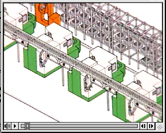
The vido screen print illustrates a modern manufacturing cell/ system under distributed control. (At the top right hand side notice the Automated Storage and Retrieval System, then the railed cart, painted orange, that provides the material handling link between the ASRS and the processing stations/ machine tools. Also notice the overhead transportation system, in the front, used for tools between the tool-store and the individual Automated Tool Storage/ Changer systems). (Courtesy of Yamazaki Mazak, Japan).
An enterprise - wide IT system architecture
The 'big picture' is always exciting because it shows the difference between efficient and wasteful enterprise information systems.
The concept illustrated below, courtesy of DEC, gives a simplified view of the way the sensors and machine processes are integrated with the PLC (Programmable Logic Control) and other devices, running fast fieldbus and profibus networks at cell control level, as well as with the plant and then with the enterprise-wide systems.
As part of a team, discuss, or if you are studying on your own, think about the following:
Preferably as part of a team, discuss and consider the following:
In this video program Mr. Wim Onink discusses the following:
Based on the presentations consider and discuss the following...
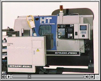
In this image (taken from the original digital video clip) you can see a small CNC lathe with an integrated robot arm that is employed to load and unload parts from a buffer (this can be seen on the left hand side of the image) to the machine tool under CNC control (Computer Numerical Control). Obviously the loading/ unloading robot's controller must communicate with the machine tool's CNC controller to avoid any conflicts. (Note, taht a "conflict" in this case can mean that the robot crashes the part into the sliding door, or the chuck of the machine, and others).
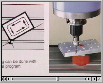
In this image (taken from the original digital video clip) you can see a vertical CNC mill with a probing head aligning the co-ordinate axes of the part program with the actual part. The benefit of this technique is that even if the part is loaded onto the machine with some error, however small that error is, the machine will automatically correct this by re-aligning itself. This particular Hitachi-Seiki machine can re-align itself in 3D. (This is an advanced feature. Most machines can do this only along 2 axes).
Based on the presentations consider and discuss the following...
Based on the presentations consider and discuss the following...