ADAM with IT is About Advanced Design and Manufacturing and Cyberspace Product and Service Reviews in our Virtual Exhibition Hall, Including the Latest News, the Most Innovative International Products & Services, New Strategies, R&D, and more...
ADAM: R&D Article
A Web-enabled Virtual Disassembly Manager (web-VDM) for Electronic Product / Process Designers, Disassembly Line Managers and Operators, a UML (Unified Modeling Language) Model of our Generic Digital Factory, and Some of Our Electronic Support System Analysis Tools
by
Paul G. Ranky
Professor, The Department of Industrial and Manufacturing Engineering, New Jersey Institute of Technology, MERC (Multi-lifecycle Engineering Research Center), Newark, NJ, 07102, USA. Email: ranky@njit.edu
Reggie J. Caudill
Director, MERC (Multi-lifecycle Engineering Research Center), NJIT, Professor, Department of Industrial and Manufacturing Engineering, Newark, NJ, 07102, USA, Email: caudill@njit.edu
Ketan Limaye
Computer Modeling Engineer, NDCEE Task 228: DEER 2 Program, Concurrent Technologies Corporation, Largo, FL 337773-5026 Email: limayek@ctc.com
Najeeb Alli
Systems Manager, New Jersey Institute of Technology, MERC (Multi-lifecycle Engineering Research Center), Newark, NJ, 07102, USA, Email: alli@njit.edu
Satishkumar ChamyVelumani, Apoorva Bhatia and Manasi Lonkar
Graduate Research Students, NJIT, MERC (Multi-lifecycle Engineering Research Center), Newark, NJ, 07102, USA
Published by ADAM with IT at http://www.cimwareukandusa.com, © Copyright by CIMware Ltd. UK and CIMware USA, Inc.
Please feel free to download this paper with its full contents, FREE of charge, but always mention the website: http://www.cimwareukandusa.com and the author(s) as the source!
Website: http://www.cimwareukandusa.com
Email: cimware@cimwareukandusa.com

Go to Welcome Page
Go to ADAM
Address: Paul G. Ranky, Dr. Techn/PhD, Full, Tenured Research Professor, The Department of Industrial and Manufacturing Engineering, New Jersey Institute of Technology, Newark, NJ 07102, USA, Email: ranky@njit.edu, or via the publishers: cimware@cimwareukandusa.com
Please note, that this article is an extended and web-formatted 3D interactive multimedia version of our article entitled: 'A Web-enabled Virtual Disassembly Manager (web-VDM) for Electronic Product / Process Designers, Disassembly Line Managers and Operators, and our UML Model and Tools', and software presentation at the IEEE International Symposium on Electronics & the Environment, San Francisco, May 2002, USA.
Abstract
The Web-enabled Virtual Disassembly Manager (web-VDM) for Electronic Product / Process Designers, Disassembly Line Managers and Operators project is a major MERC / NJIT R&D (Multi-lifecycle Engineering Research Center) group effort, supported by several funding agencies, companies and institutions and their hard working staff and RAs (Research Assistants).
The purpose of this paper is to introduce a segment of this project, by discussing object oriented, validated modeling methods and software tools, as well as a system architecture in UML (Unified Modeling Language) that enables individual, as well as eCommerce-linked, B2B (business to business) collaborative enterprises to analyze and design all critical aspects of their demanufacturing and logistics processes over the web, manage their disassembly lines and provide electronic support systems for operators. (Please note, that other papers at this conference, as well as papers published elsewhere discuss other aspects and subsystems of our integrated web-VDM architecture).
Besides an overview of our system model, this paper focuses on specific, web-enabled electronic support tools for eCommerce of harvested components and parts, as well as tools for disassembly line managers and operators. Furthermore, integrated with the above system, we demonstrate our tools, and our novel 3D part identification and electronic object/ component marking method, that helps line managers to identify physical objects/ components electronically and then publish these objects over the web as part of our webVDM database.
Keywords
Demanufacturing, Logistics Process Model, Disassembly Line Management, Virtual Disassembly, Disassembly User Requirements Analysis, Enterprise Model in UML (Unified Modeling Language), Disassembly Failure Risk Analysis. eCommerce, Collaborative Enterprises, Demanufacturing Software Tools.
Introduction
We have used UML, the Unified Modeling Language (an industry-standard, object-oriented software and system analysis/ design and documentation method), as a language for specifying, constructing, visualizing, and documenting the artifacts of a software-intensive system, such as web-VDM, and targeted the modeling efforts to describe concurrent, distributed systems, such as the electro-mechanical demanufacturing systems we have studied at our industrial partners’ sites.
We need to understand, therefore model and then control e-Commerce-linked supply chains / value chains in the DFE context. The heart of our reusable model is written in UML (Unified Modeling Language), extended with our object and component oriented B2B process models, as well as our demanufacturing line scheduling, balancing and production control algorithms coded in Java, and executed as Java applets over intranet, or Internet web-pages.
Having completed the generic architecture, by following system analysis and design research using the CIMpgr process modeling methodology, and UML (Unified Modeling Language) use-cases, class and object diagrams, and activity diagrams, web-enabled code was generated in Java to populate our classes of objects and object databases. Then we have added to our models and tools the desired behavior and interaction to reflect the requirements identified between collaborating B2B demanufacturing enterprises. ([1] to [3]).
Furthermore, our system includes a novel, graphically-oriented disassembly process planning method that considers process attributes, such as inputs, outputs, resources (including disassembly tools, fixtures and human skills), and constraints, offers process descriptions in a variety of formats, including text, images, videos, 3D animations, and 3DVR (three dimensional virtual reality) objects that are interactive, integrated with an object-oriented disassembly failure risk and effect analysis tool (OO_DFRA), as well as with our requirements analysis tools (CORA) and design of experiments tools.
This is our Taguchi DOE (extended 3D Design of Experiments) Calculator, subject of an other paper, helping line managers and operators to identify and learn about disassembly failure risks and best practices in cases when data is not available, therefore experiments have to be designed using statistical methods.
A novel feature of our solution is that in our databases, besides traditional text, image and code objects and components, we create and use 3D web-objects, enabling users to access interactive 3D components, interactive 3D videos, and 3D animations for the purpose of capturing and/ or communicating complex knowledge in a simple fashion truly anywhere and anytime over the web, and/or via secure factory intranets and extranets; as required.
At a higher level, our UML (Unified Modeling Language) models (in Rational Rose 2000) and Java code are open source, generic and scale able to a variety of different audiences, including the knowledge workers, in design, manufacturing and demanufacturing, eCommerce and marketing, and demanufacturing line managers and operators, who are increasingly mobile and global. ([4] to [8]).
The obvious choice to the above outlined challenge was to research and develop an object / component oriented approach, that is essential not only for technical, marketing and management reasons, but also very useful because it supports total quality principles, in particular trace ability aspects of TQM (ISO 9000:2000).
Furthermore, our model can be specifically useful for capturing design, manufacturing/ assembly, DfE and service/ maintenance related best practices, for supporting and educating DfE designers, maintenance technicians and operators along demanufacturing lines, as well as for asset recovery and eCommerce operations.
Our Class Model in UML
We have developed our B2B eCommerce-linked, collaborative demanufacturing class model in UML. The Unified Modeling Language provides system architects working on object analysis and design with one consistent language for specifying, visualizing, constructing, and documenting the artifacts of software systems, as well as for business modeling. We have applied this widely used, generic method to demanufacturing enterprise modeling as well as to line and operator support and production planning environments, within a large, very detailed system model that we have created in UML and CIMpgr for B2B, eCommerce collaborative, global, DfE corporations. ([8] to [15]).
One of the primary goal of our UML model within web-VDM is to advance the state of the industry by offering object / visual modeling tool interoperability for analysis, tool development and simulation purposes. In order to enable meaningful exchange of model information between tools, agreement on semantics and notation is required, nevertheless our basic architecture is generic, therefore it is relatively easy to customize our models to particular demanufacturing enterprises as required.
Our UML model for collaborative demanufacturing web-VDM enterprises meets the following requirements:
- Offers a formal definition of a common object analysis and design (OA&D) meta model to represent the semantics of web-VDM OA&D models, which include static models, behavioral models, usage models, and architectural models.
- Provides specifications for mechanisms for model interchange between OA&D tools, including our process modeling tools in CIMpgr, the OO/CO_DFRA Tool that we have developed (Object oriented/ Component oriented Disassembly Failure Risk Analysis Tool, as discussed below), and our CORA Tool (Component Oriented Requirements Analysis Method and Tool, as discussed in our second paper at this conference)
Our UML models define human-readable notation for representing OA&D models for web-VDM. This notation is an essential part of our mission, in that we offer open source, web-enabled, graphically intensive, easy to follow solutions at all levels of our system.
Our UML class diagram is a small, but important part of our system model, nevertheless it illustrates the breath and the depth of our efforts. Our class diagram shows a set of classes, interfaces, and collaborations an their relationships that are generic in the demanufacturing business. The actual classes describe all important aspects of eCommerce-linked DfE enterprises, including design, marketing and sales, demanufacturing, disassembly, part harvesting and the sale of demanufactured parts over intranets and the Internet, and even disassembly line management and operator support systems.
A unique feature of our models is that as we gradually disassemble a device or a machine, such as a PC, besides various disassembly analysis processes, we integrate interactive 3D objects in our databases of our parts and components, as well as if necessary support managers, designers and operators with 2D and 3D videos, interactive part identification systems and other, advanced multimedia solutions over secure intranets, or the Internet.
We illustrate this here by showing only a few of the many already created, downloadable 3D files of an old PC, the very first dual floppy IBM manufactured PC, that we have disassembled for the purpose of this analysis. Please note, that you will need QuickTime ver 5. or later FREE from http://www.apple.com/quicktime/download to run these typically 2 to 5 Mbyte 3D files. (Note, that for this paper we have rendered them at high, full screen quality. Optionally rendered at smaller size, the file sizes can be as small as 400K to 1 Mbyte). When the file has been downloaded, click on the poster frame of the image, and then move the mouse left and right to enjoy the 3D views of these historic objects. The files we have included in this paper are as follows: the assembled PC, the stage when the power supply has been taken out, and then some of the components that are harvested, such as the PC frame, the bus cable, and a floppy drive.
For a system like this, the database is central; the main components are as follows: Software, Hardware, VendorDetails, ProjectHistory, Contract and CustomerDetails. Each of these classes have attributes and functions associated with them, and were designed to cover the model of globally networked, collaborative B2B corporations in the DfE business.
Let us illustrate the simplified process model (using DFD, a dataflow diagramming method) and the UML model we have created. The DFD model illustrates the various major processes collaborative, eCommerce enabled enterprises have to execute in order to be able to sell/ purchase new, as well as dissassembled, harvested components.
.
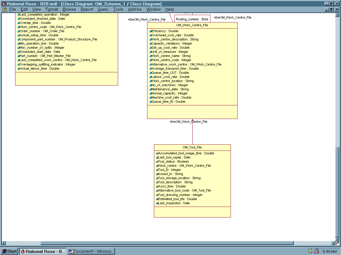
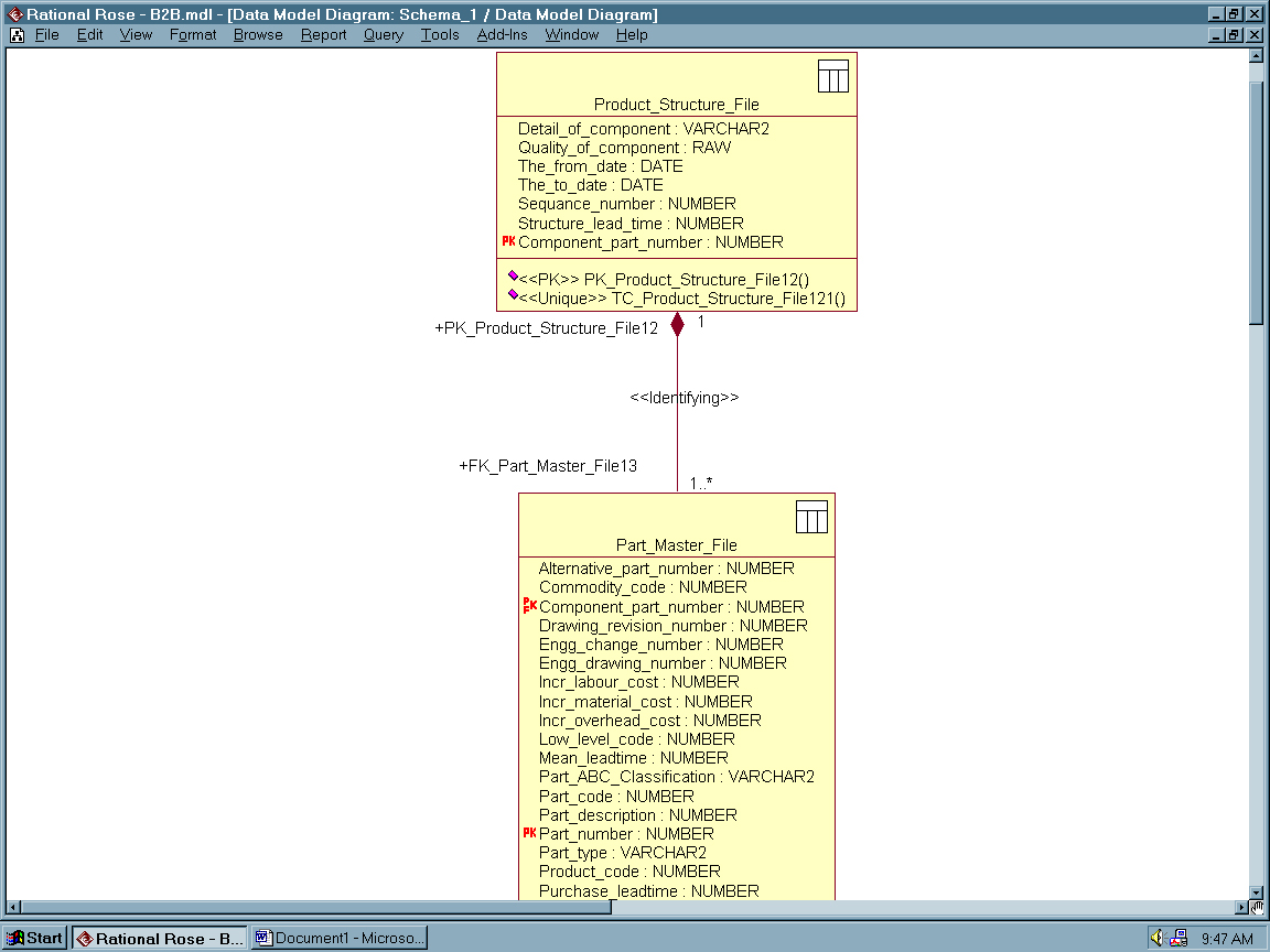
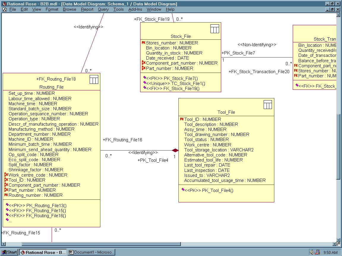
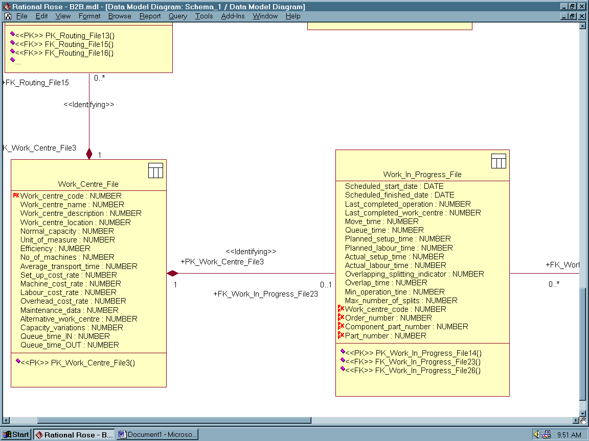
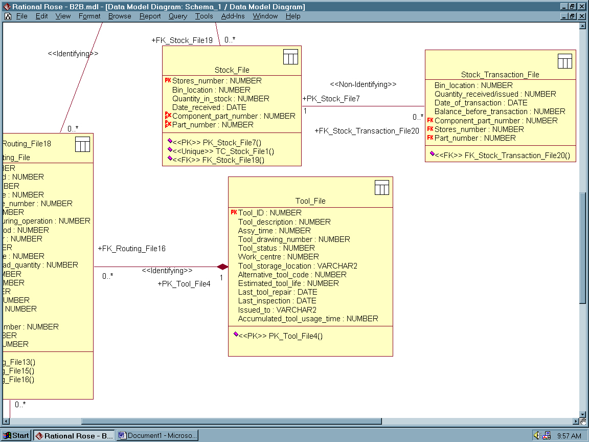
The UML diagrams below, illustrate a more detailed system analysis/ design and database implementation plan that specify our thinking, models and simulation more accurately. (Please note, that due to the large size of our model, we have taken screenprints, and then converted them into a web-enabled graphics format. This way the Rational Rose 2000 programmed/generated diagrams became clear and readable over the web too).

.
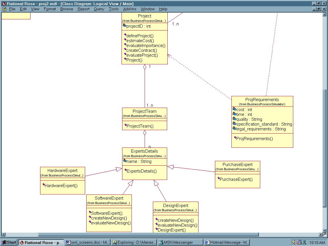
.
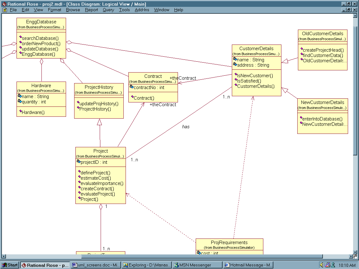
.
Having shown the main class diagrams, let us turn our attention to the contents and description of our files.

.
.
.
.

.
.
.

.
.
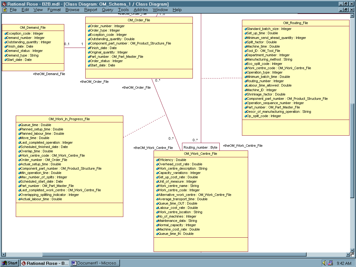
To illustrate some further detail at which we have modeled our web-collaborative enterprises, as an example, consider the Disassembly Work Center Files and the Disassembly Tool / Fixture Files in text form ([7]) below (as integrated in the full UML models above):
Disassembly WORK_CENTRE_FILE
Work_centre_code (a unique identification code) of the part number )
Work_centre_name
Work_centre_description
Work_centre_location
Normal_capacity
Unit_of_measure_for_the_capacity [mins]
Efficiency
Number_of_machines (where a group of machines is identified)
Average_transport_time (average transportation time to other work centres)
Set_up_cost_rate
Machine_cost_rate
Labour_cost_rate
Overhead_cost_rate
Maintenance_data
Alt_work_centre_ID (alternative work centre at which similar work could be performed if available)
Capacity_variations
Alt_work_centre_name
Alt_work_centre_capacity
Alt_work_centre_description
Queue_time_IN (queue time before processing)
Queue_time_OUT (queue time after processing)
Disassembly TOOL_FILE
Tool_ID (a unique identification code of the tool)
Tool_description
Assy_time (tool assembly time)
Tool_drawing_number
Tool_status
Work_centre_code (the work centre in which the tool is being used)
Tool_storage_location
Alt_tool_code (alternative tool which may be used)
Estimated_tool_life
Date_of_last_tool_repair
Date_of_last_inspection
Issued_to(operator name)
Accumulated_tool_usage_time
To summarize this section, we have used UML as a language for specifying, constructing, visualizing, and documenting the artifacts of a software-intensive system, such as web-VDM, and targeted the modeling efforts to describe concurrent, distributed systems, such as the electro-mechanical demanufacturing systems we have studied at our industrial partners’ sites.
The Developed and Validated OO/CO_DFRA Tool (Object Oriented/ Component Oriented Disassembly Failure Risk Analysis Tool)
Based on our UML collaborative demanufacturing models introduced briefly above, as well as based on the requirements analysis exercises, by using our CORA Tools, we have created the Disassembly Failure Risk Analysis (DFRA) Tool.
This is a disassembly failure mode and effect analysis method. It represents a systematic method developed for disassembly processes to identify and minimize potential failure risks / failures of disassembled sub-assemblies, objects and components, and their effects on the customer (meaning internal and external customers).
DFRA is a Team Oriented Problem Solving (TOPS), method, aimed at minimizing dissatisfaction, and financial loss within the collaborative web-VDM corporations (see again our UML models above).
DFRA is applied during the planning stages of a disassembly process, and then updated on a regular basis to document changes. It addresses negative quality and is primarily concerned with potential events, that can make the disassembly process, or the harvested components fail.
Our approach is component-oriented, meaning that as we disassemble the product the DFRA Team focuses on each subassembly and then component.
In our system, a component is a disassembled part, that we do not plan to disassemble further (even if we could, e.g. a hard disk drive, or a power supply unit), that is worthwhile to harvest either for resale, or for environmental reasons. (Note, that sometimes such objects are disassembled for hazardous and/or other reasons; which our tools can handle too).
DFRA is an iterative technique that promotes systematic, modular design oriented engineering thinking when a new disassembly process and/or product or system is developed, by the DFRA TEAM, in terms of:
- What could go wrong with the product or the processes involved when disassembling the product?
- How badly might it go wrong? What are the effects? How serious is the potential damage?
- What needs to be done to prevent failures? (including tools, fixtures, operator training and others issues).
The values we enter into a DFRA spreadsheet are on a relative scale, determined by the local DFRA Team, as well as by the local, customized standards they follow. ([17] to [21]).
Often, such disassembly risk rating values and standards are industry wide, enabling teams to compare data, and learn from each other. In order to support this standardization process for the disassembly industry, we have included three important files. These being the disassembly failure risk rating rules, regarding Severity, Detection and Occurrence. (Please note, that during the live software demonstration we’ll explain these rules in more detail using validates industrial cases).
Live Code Software Demonstration
As demonstrated during our conference presentation using live code, for our purposes DFRA is implemented as a specific spreadsheet tool, with several 3D objects, and web-links, focusing on disassembly only. (Note, that the method, relying on the fundamental principles of failure mode and effect analysis, can be applied to a variety of other aspects of the total life cycle process, including product/ process design, manufacturing, assembly, maintenance processes, and many others, in a variety of industries).
To summarize this section, our approach follows the logic, that in industry different failure risks, and/or modes, and their effects are typically analyzed by a team of engineers working with some objective, cross functional teams representing "fresh eyes" and new ideas. In our case the DFRA Team focuses on disassembly processes of electro-mechanical devices, including PCs.
Conclusions
The created model, the Java code written, our validated tools, and the 3D object databases can be accessed and data mined for a variety of applications, including B2B e-Commerce-based logistic DfE supply chain / value chain analysis, dynamic simulation, demanufacturing marketing and sales support, for line management and operator support, and for other purposes.
The generic methodology developed focuses on all critical objects and components in the above listed disciplines, including their process parameters and their interactions with the relevant networked (web) databases.
Furthermore, it integrates various process inputs, acting at different priorities from several different sources, including the web, constraints under which the processes must fire, and resources, that the processes must use in order to be able to produce outputs that represent value.
Our validated method follows an open systems architecture that enables “third party” processes to be integrated into, and/or to interact with. By following internationally accepted total quality and environmental standards, important rules learned can be fed back to the product/ process design team, as well as to all support systems and personnel, most importantly to the multi-lifecycle engineering design, manufacturing/ assembly planning, quality and eCommerce marketing teams.
Acknowledgements
This work is partially being funded under a subcontract with DEER2, Task 228 of the National Defense Center for Environmental Excellence (NDCEE), a U.S. Department of Defense (DOD) contract operated by CTC.
Special thanks are expressed to Rational Software Inc., USA, for donating a site license of Rational Rose 2000 (UML Tool) to P.G. Ranky, NJIT, and M. F. Ranky at http://www.cimwareukandusa.com for his valuable contributions in creating with P. G. Ranky the 3DVR web-object methodology and for programming the actual 3D objects.
References
[1] Ranky, P.G.: An Object Oriented System Analysis and Design Method (CIMpgr) and an R&D Case Study, ADAM with IT (Advanced Design And Manufacturing), An international internet registered R&D journal hosted by: http://www.cimwareukandusa.com listed and indexed by the Association of Research Libraries, Washington DC, USA, and the Edinburgh Engineering Virtual Library, UK. 20 p., Vol. 1., April 1999.
[2] Ranky, P. G.: Some Analytical Considerations of Engineering Multimedia System Design within an Object Oriented Architecture, IJCIM (International Journal of CIM, Taylor & Francis, London, New York) ), Vol. 13, No. 2, May 2000, p. 204-214
[3] Ranky, P.G.: Engineering Multimedia in CIM (Computer Integrated Manufacturing), IJCIM (International Journal of CIM, Taylor & Francis, London, New York, ), Vol. 13, No. 2, May 2000, p. 169-171
[4] Ranky, P.G., Das, S and Caudill, R: A Web-oriented Virtual Product Disassembly and Identification Method for DFE (Design for Environment) and Electronic Demanufacturers, 2000 IEEE (USA) International Symposium on Electronics and the Environment, Organized by IEEE (USA), and the Computer Society, USA, May, 2000, San Francisco, CA, USA, Conference Proceedings.
[5] Ranky, P G.: A Multimedia Web-based Flexible Manufacturing Knowledge Management Framework, Japan-USA International Symposium on Flexible Automation, ASME (American Society of Mechanical Engineers), July, 2000, Ann Arbor, MI, Conference Proceedings.
[6] Ranky, P G.: An Object Oriented Virtual Concurrent Engineering Model and Product Demonstrator Case Study, Japan-USA International Symposium on Flexible Automation, ASME (American Society of Mechanical Engineers), July, 2000, Ann Arbor, MI, Conference Proceedings.
[7] Ranky, P G: Manufacturing Database management and Knowledge Based Expert Systems, Cimware Ltd. UK, ISBN 1-872631-03-7, 240 pp. 1990.
[8] Ranky, P G: The Design and Implementation of a Case-based Learning Library for Engineering, Management and Computing Education using Interactive 3D - web Technology, Second Annual Best Practices Showcase, NJ Higher Education Network, Proceedings, the Seaton Hall University, Newark, NJ, Nov 17, 2000
[9] Upcraft, S and Ranky, P G: A Case Based Introduction to Rapid Prototyping Solutions, An Interactive Multimedia Presentation on CD-ROM with off-line Internet support (650 Mbytes, approx. 150 interactive screens, 50 minutes of digital videos, animation and 3DVR objects), by CIMware (IEE and IMechE Approved Professional Developer), 2000-2002, ver 2.0. Multimedia design & Programming by P G Ranky and M F Ranky.
[10] Frazer, A. and Ranky, P.G.: A Case-based Introduction to the National Electronics Manufacturing Initiative (NEMI) Plug and Play Factory Project; An interactive multimedia publication with 3D objects, text and videos in a browser readable format on CD-ROM/ intranet by http://www.cimwareukandusa.com, CIMware USA, Inc. and CIMware Ltd., UK, ISBN 1-872631-41-x, 2000-2002. Multimedia design & programming by P G Ranky and M F Ranky.
[11] Analysis Patterns, Reusable Object Models, M. Fowler, Addison Wesley Longman, Inc., 1999, 357 pp., ISBN 0201895420
[12] Applying Use Cases, A Practical Guide, G. Schneider and J. P. Winters, Addison Wesley Longman, Inc., 1999, 188 pp., ISBN 0-201-30981-5
[13] Building Scalable Database Applications, Object-Oriented Design, Architectures, And Implementations, P. M. Heinckiens, Addison Wesley Longman, Inc., 2001, 311 pp., ISBN 0-201-31013-9
[14] Building Scalable Database Applications, Object-Oriented Design, Architectures, And Implementations, P. M. Heinckiens, Addison Wesley Longman, Inc., 1998, 311 pp., ISBN 0-201-31013-9
[15] Building Web Applications With UML, J. Conallen, Addison Wesley Longman, Inc., 2000, 300 pp., ISBN 0-201-61577-0
[16] Russomanno D J: Function-centered framework for reasoning about system failure and multiple levels of abstraction, Expert Systems, v16, n3, 1999, Learned Information Europe Ltd., Oxford, p 148-169.
[17] McCollin, C: Working around failure, Manufacturing Engineer, v78, n1, 1999, IEE, Stevenage, England, p 37-40.
[18] Nquyen, D: Failure modes and effects analysis for software reliability, Proc. of the Annual Reliability and Maintainability Symposium, Int'l Symposium on Product Quality and Reliability and Integrity, Jan 22-25, 2001, Philadelphia, PA, USA, p. 219-222.
[19] Huang G Q et al: Failure mode and effect analysis (FMEA) over the WWW, University of Hong Kong, International Journal of Advanced manufacturing Technology, v16, n8, 2000, Springer Verlag London, p 603-608.
[20] Bot Y: FMECA modeling - a new approach, Proc. of the Annual Reliability and Maintainability Conference, Jan 18-21, 1999, Washington DC, USA, p 25-28.
[21] Throop D R et al: Automated incremental design FMEA, Boeing Co., IEEE Aerospace Conference Proc., 2001, IEEE, May 10-17, 2001, p 73451-73458.