ADAM is About Advanced Design and Manufacturing with Information Technology, and Cyberspace Product and Service Reviews in our Virtual Exhibition Hall, Including the Latest News, the Most Innovative International Products & Services, New Strategies, R&D, and more...
ADAM: R&D Article
Ranky, P.G.: Digital Factory and Digital Car Modeling with UML and OPNET Network Simulation Tools
Published by ADAM at http://www.cimwareukandusa.com, © Copyright by CIMware Ltd. UK and CIMware USA, Inc.
Please feel free to download this paper with its full contents, FREE of charge, but always mention the website: http://www.cimwareukandusa.com and the author(s) as the source!
Website: http://www.cimwareukandusa.com
Email: cimware@mac.com

Go to Welcome Page
Go to ADAM
Address: Paul G. Ranky, Dr. Techn/PhD, Full Tenured Research Professor, The Department of Industrial and Manufacturing Engineering, as well as the Department of IT, New Jersey Institute of Technology, Newark, NJ 07102, USA, Email: ranky@njit.edu
Abstract
Jump to top
In order to support automotive designers and manufacturers in their efforts to collaborate with globally distributed suppliers and collaborating designers and manufacturers, to demonstrate and support their products, as well as to communicate customer feedback to their design department, we have researched and then developed a generic digital factory, and digital car model, and a methodology by focusing on key processes, objects and their interactions, and created a software tool-set that will systematically assist and support engineers and managers to analyze requirements and processes along value flows, process-related risks, and develop virtual product demonstrations, and support advanced telematics applications as part of the on-board and off-line Driver Information Systems (DIS), following a quantitative and computational approach (Ranky, 2002a, 2002b, and 2003).
To summarize, the challenge we address in this paper is that we model the digital automotive factory, as well as the digital / telematic car as an integrated system, that is designed, manufactured, maintained, monitored, controlled, and supported throughout its multiple lifecycles in a web-collaborative fashion, using analytical, quantitative and open-source computational methods. (Ranky, 1997, 2002).
Please note, that based on the 3D Multimedia eBook presentation of this paper, the SAE International (The Engineering Society For Advancing Mobility, Land, Sea, Air and Space, USA) has awarded this work with a Certificate of Appreciation in 2003. (See the Certificate).
Introduction
As it happens in literally all aspects of life in our 'knowledge age', the modern automotive consumer is demanding high quality, reliable, safe, lower cost, environmentally friendly and easier to use product. This requirement drives engineers, and forces management to think of new methods in terms of on-board automotive sensor-to-software solutions, better and more efficient engine management and control systems, telematic systems (a specialized area of automotive multimedia and real-time networking) for driver information systems, repair and passenger entertainment.
At the factory level, the traditionally very conservative automotive industry has realized, that it needs to implement some major changes in its entire life-cycle design and consumer support systems. These changes are fuled by an ever increasingly educated customer, who can check prices, availability, and quality/ safety test results, service issues and others on the Internet before purchasing the product.
The big push now is to keep the auto-industry more profitable and environmentally friendly, by simultaneously making it leaner and agile at the design, manufacturing, assembly and demanufacturing side, to benefit the manufacturers, and more efficient, more individualized and real-time monitored, safe and enjoyable during the active life-cycle part, for the benefit of the customers.
The key to all this is to establish the information system architecture between the digital factory and the digital / telematic car, including all support and maintenance systems, to balance the available fail-safe technology and the realistic cost at which the sensor-to-software integration can be delivered within the increasingly software controlled digital car, as well as outside the car. (Abdu, 2002, Ashton and Ranky, 1998, Coelingh, 2002, Ranky, 2002a).
Assuming that the advanced sensor/ software feedback controlled and networked system works in a digital automobile, the benefits are impressive.
As a few examples, consider the car that becomes a networked node in your household wireless intranet network, so that you can download your favorite MP3 files (thousands), and DVD movies (dozens) before a journey, that becomes machine 'intelligent' and warns which parts need to be changed and when to maintain safe operation, that offers dynamically adjusted navigation throughout the journey, that attempts to avoid collision when parking or in other situations, that remembers all key processes before, during and after a collision, so that responsibilities and insurance investigations can be done accurately, and fairly, that entertains their passengers as each individual prefers it without disturbing fellow passengers, and many others.
These examples open up a series of exciting R&D opportunities for the entire community of automotive engineering professionals. In this paper we address a key segment, the digital automotive factory model, as well as the digital / telematic car model, as an integrated system. In other related papers and publications we further demonstrate our methodology and software-toolset using various industrial and research case studies. (Culp, 2002, Dilich, 2002, Gautschi, 1998, Harrison, 2002, Karimi, 2002, Matsunaga, 2002, Nakae, 2002, Nasr, 2002, Ranky and Ranky, 1997, Ranky, 2002a, 2002b, and 2003).
A SOLUTION: CONCURRENT / ENGINEERING BASED ON THE QUANTITATIVE AND COMPUTATIONAL DIGITAL FACTORY AND DIGITAL / TELEMATIC CAR MODEL, AND OUR SOFTWARE TOOL-SET
Our solution to the above challenge is that we model the digital automotive factory, as well as the digital car as an integrated, networked system of objects, that is designed, manufactured, maintained, monitored, controlled, and supported throughout its multiple lifecycles in a web-collaborative fashion, using an analytical, quantitative and computational concurrent / simultaneous engineering approach.
Concurrent (or Simultaneous, meaning the same) Engineering in this respect is a new approach to collaborative, digitally networked, and feedback controlled product development. It focuses on parallel (vs. sequential) interaction among various traditional and digital product life cycle concerns. In other words: modern Concurrent Engineering (CE) is a systematic approach to the integrated, simultaneous, or parallel (meaning the same) design of products, their related processes, and services, including manufacture, assembly, test and multi-lifecycle product support. This approach is intended to cause developers, from the outset, to consider all elements of multiple product life cycles from conception through re-engineering, and eventual recycling and disposal, including quality, cost schedule and user requirements.
The key issue is that the system analysis of the factory or organization and the resulting new CIME (Computer Integrated Manufacturing Enterprise) architecture must take into account the flow of information, and materials, as well as the processes, seeing them as an integrated whole for the purpose of becoming lean at all levels (in other words, for cutting waste). (Ranky and Ranky, 1997, Ashton and Ranky, 1998, Ranky, 2000, Ranky, 2002, Johanssessen, 2002).
After this introduction, let us discuss our methodology and results in some more detail.
Our core model is focused on Object Oriented Virtual Collaborative Concurrent Engineering Over the 3D Internet, that enables
- Collaborating automotive marketers, engineers, and collaborative teams of designers, manufacturers, testers, re-sellers, and others to demonstrate their products in an interactive fashion,
- Potential buyers to review products in-depth over the web,
- Product design and manufacturing engineers, system integrators, marketing and sales engineers to analyze and learn innovation, design, system integration, maintenance and other challenges that the virtual 3D web-enabled demonstration of such products can automatically collect, categorize and then feed back to the appropriate managers, as well as
- Allow manufacturers to create sophisticated 3D virtual reality, web-enabled Virtual Product Demonstrations (3D_VPD) that can be built easily and in a very short time.
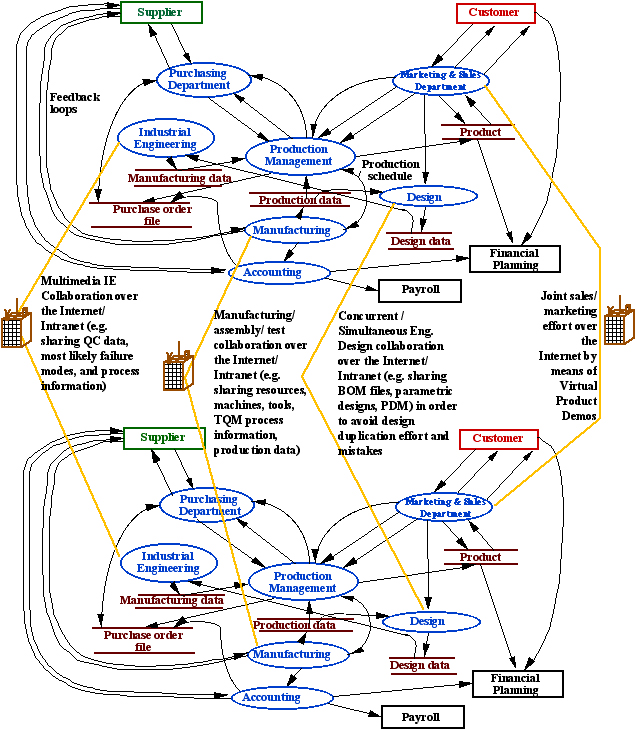
Figure 1 illustrates the basic collaborative activities of two simplified ‘digital factories’, using dataflow diagrams, as the modeling tool. By studying the key processes (modeled as ellipses) and the interactions/ data flows between the processes and the data stores (modeled as two parallel lines), and the data sources and sinks (modeled as boxes), one can follow the value chain along the processes and make the collaborating organizations leaner and eventually minimize waste. As a result, the competitive advantage gained will be enormous because for a company empowered with the development tool-set the time it will take to demonstrate and market a new product on the internet will collapse to that of the fraction it takes and costs without it. Furthermore with the added product intelligence gathered from customers, innovation will accelerate and designs, and manufacturing / assembly processes and quality will improve because everybody will learn focused and well targeted market intelligence feedback.
In more detail our software tool-set offers the following features:
- Visually demonstrate the product in an attractive way (i.e. photos, videos, animation, 3D virtual reality 'walkthroughs', 3D virtual object movies and others)
- Let the potential user try and test the basic and [optionally the advanced] functionality of the product (in a virtual fashion)
- Enable the potential user to test the durability and quality of the product in a virtual fashion
- Allow the potential customer to unpack and install a factory packed device and operate it (e.g. an automobile accessory, replacement parts, an automotive DVD player, and others) in a virtual fashion
- Provide system integration, connectivity information, and other advice on 'plug & play' features that are important for decision makers
- Allow access to the User Manual of the product with hotlinks within the interactive multimedia talking book-style manual
- Allow access to the Programming Manual of the product
- Allow access to legal, licensing and warranty information, using the user’s language, versus that of the legal text only,
Our system will make a significant impact in the following areas:
- Significantly reduce the overall cost of introducing and demonstrating a new product, anywhere in the world, anytime, literally real-time, 365 days a year,
- Greatly improve the quality of the user support system by offering the outlined advanced electronic support system anytime, anywhere,
- Educate the user and others, such as university students, technicians in colleges, at various levels, anytime, anywhere,
- Test market new products by using virtual products and real visitors on a virtual basis, by collecting, analyzing, structuring, extracting and then feeding back valuable data from them from the point of attraction through product setup, installation, test-ride, and disposal.
OUR DIGITAL FACTORY AND DIGITAL CAR CLASS MODELS IN UML
We have developed our B2B eCommerce-linked, collaborative digital factory class model in UML. The Unified Modeling Language provides system architects working on object analysis and design with one consistent language for specifying, visualizing, constructing, and documenting the artifacts of software systems, as well as for business modeling. We have applied this widely used, generic method to design and manufacturing enterprise modeling as well as to line and operator support and production planning environments, within a large, very detailed system model that we have created in UML and CIMpgr for B2B, eCommerce collaborative, global, DfE corporations.
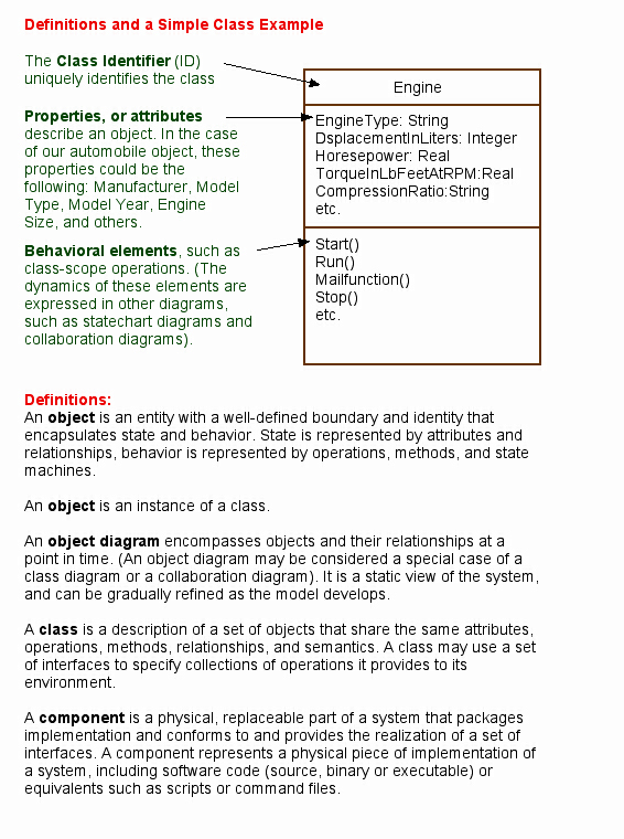
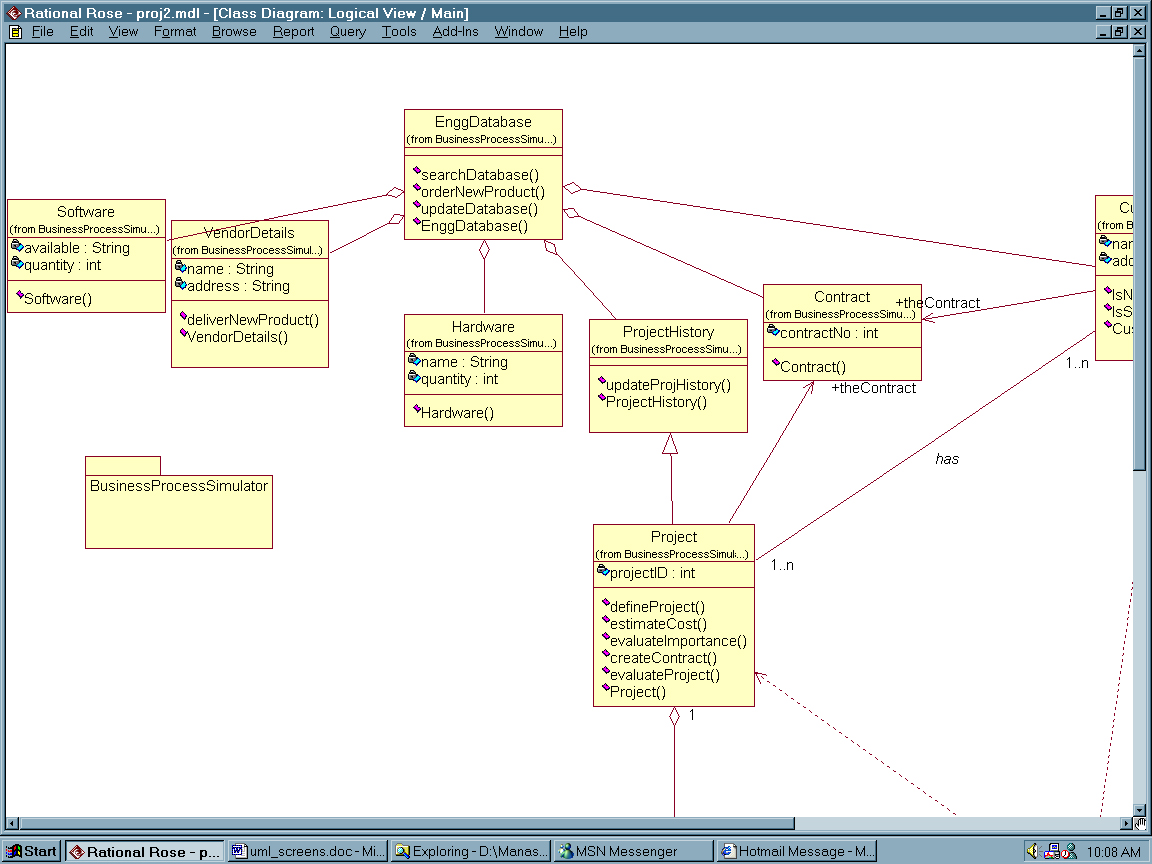
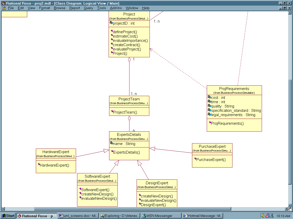
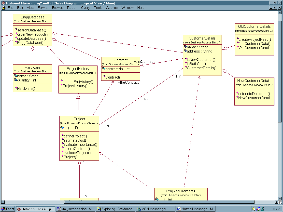
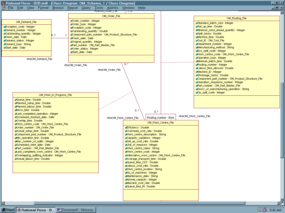
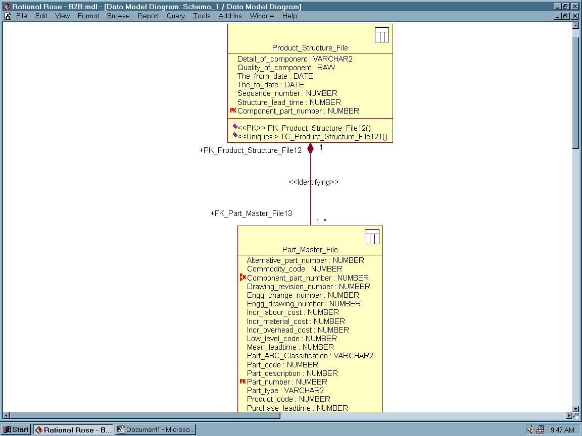
Figure 2 illustrates some key definitions we use in our ‘digital factory’ and ‘digital car’ class models, and Figures 3, 4, 5, 6, 7 , 8 and 9 illustrate some of our key ‘digital factory’ in UML (Unified Modeling Language) models. As it can be seen in these more formal models, we model all key processes/ classes of generic digital factories, capable of marketing, designing, manufacturing, testing and maintaining concurrently engineered products (as illustrated in Figure 1).
One of the primary goal of our UML model within web-VPD (Virtual Product Demo) is to advance the state of the industry by offering object / visual modeling tool interoperability for analysis, tool development and simulation purposes. In order to enable meaningful exchange of model information between tools, agreement on semantics and notation is required, nevertheless our basic architecture is generic, therefore it is relatively easy to customize our models to particular de-manufacturing enterprises as required.
Our UML model for collaborative digital enterprises meets the following requirements:
- Offers a formal definition of a common object analysis and design (OA&D) digital factory and digital car meta model to represent the semantics of 3Dweb-VPD OA&D models, which include static models, behavioral models, usage models, and architectural models.
- Provides specifications for mechanisms for model interchange between OA&D tools, including our process modeling tools in CIMpgr, the OO/CO_DFRA Tool that we have developed (Object oriented/ Component oriented Disassembly/ Process Failure Risk Analysis Tool, as discussed below), and our CORA Tool (Component Oriented Requirements Analysis Method and Tool).
- Our UML models define human-readable notation for representing OA&D models for 3Dweb-VPD. This notation is an essential part of our mission, in that we offer open source, web-enabled, graphically intensive, easy to follow solutions at all levels of our system.
- Our UML class diagram is a small, but important part of our system model, nevertheless it illustrates the breath and the depth of our efforts. Our class diagram shows a set of classes, interfaces, and collaborations an their relationships that are generic in the de-manufacturing business. The actual classes describe all important aspects of eCommerce-linked digital enterprises, including design, marketing and sales, de-manufacturing, disassembly, part harvesting and the sale of de-manufactured parts over intranets and the Internet, and even disassembly line management and operator support systems.
A unique feature of our models is that besides various analysis processes, we integrate interactive 3D objects in our databases of our parts and components, as well as if necessary support managers, designers and operators with 2D and 3D videos, interactive part identification systems and other, advanced multimedia solutions over secure intranets, or the Internet.
For a system like this, the database is central; the main components are as follows: Software, Hardware, VendorDetails, ProjectHistory, Contract and CustomerDetails. Each of these classes have attributes and functions associated with them, and were designed to cover the model of globally networked, collaborative B2B corporations (or ‘digital factories’).
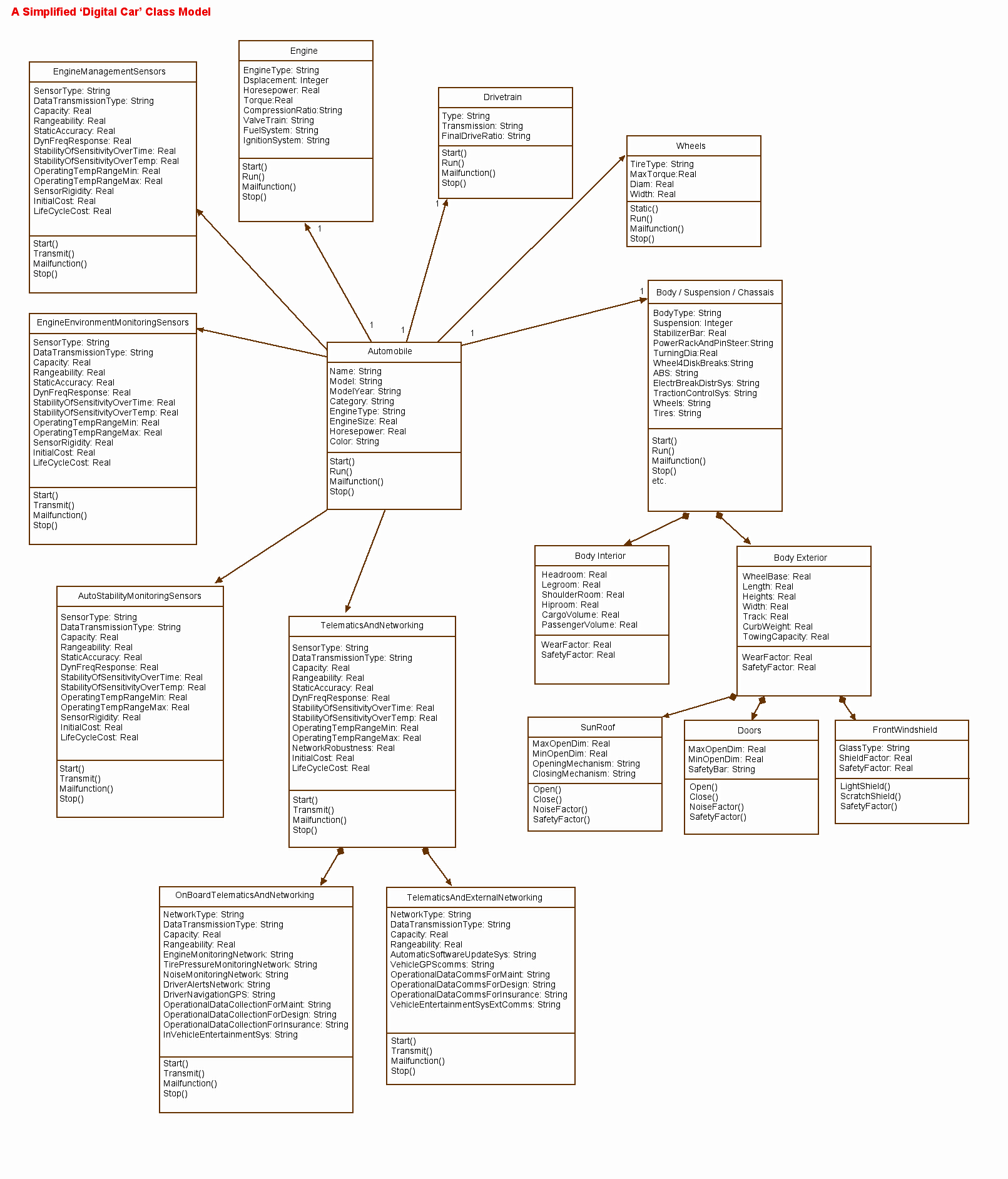
As stated above, in order to be able to analyze the benefits of an integrated approach to lean, concurrent engineering, besides the digital factory models, we have created digital car models too, as shown in Figure 10. Our simplified Digital Car class model in UML illustrates the potential links to our digital factory information systems, as well as the major classes of objects within the networked telematics environment of a modern automobile.
As can be seen, we have used UML as a language for specifying, constructing, visualizing, and documenting the artifacts of a software-intensive system, such as our digital factory and digital car models, and targeted the modeling efforts to describe concurrent, distributed systems, such as the design and manufacturing/ assembly and after-sales support, including maintenance of automobiles.
In the following section of the paper we’ll illustrate a few potential application possibilities and ideas the way we see the real benefits of using our analytical and computational digital factory and digital car models.
INTEGRATED DIGITAL CAR AND DIGITAL FACTORY MODEL APPLICATION CASE: SENSORS FOR ENGINE MANAGEMENT, STRUCTURAL AND OTHER SAFETY ASPECTS OF THE AUTOMOBILE
In this case we briefly investigate how Sensors for Engine Management, Structural and Other Safety Aspects of the Automobile could be integrated into our digital factory and digital automobile models, for the purpose of maximizing the benefits of the offered technologies.
The challenge of putting sensors, and therefore obtaining data from automotive engines and structural elements of the car vary in terms of harshness and complexity of control. The main areas are heat, vibration, force and pressure sensing because by developing feedback-loops all aspects of the automobile can be improved.
One of the major problems of continuous cylinder pressure measurement is the reliability of the diaphragm. Standard pressure sensors use a diaphragm to link the pressure impact with the measuring element. These diaphragms cannot be made to withstand the mechanical load over a sufficiently high number of cycles, especially when the engine is running with heavy oil or diesel oil. Moreover, they do not resist corrosion caused by sulfur content in the fuel under prevailing thermal conditions. Any sensor technology based on a diaphragm design will lack that reliability over time.
There are two main engine monitoring technologies. These being fiber optic sensors, and the new piezoelectric technology from Kistler. Any deformation of the diaphragm, based on pressure impact, will either change the reflection intensity of the diaphragm, as the Optrand diode system, or change the distance between two mirrors inside an interferometer, as the Fabry-Perot-Interferometer, FFPI, laser system. Both of these systems convert this change from pressure into a voltage signal.
The new C-Sensor, does not depend on a diaphragm to measure pressure. Engineered as a section of a thick-walled tube, the C-Sensor attaches via a hollow bolt directly into the bore on an engine for an indicator valve assembly. Cylinder pressure is admitted through holes in the wall of the hollow bolt into a clearance area between the bolt and inner wall of the sensor. The indicator valve is simply screwed back into the head of the hollow bolt, with its function fully retained. The body of the sensor expands under the pressure and causes a tangential stress in its wall proportional to the pressure. That stress, in turn, is measured by a piezoelectric measuring element installed in the sensor wall. The system does not rely on any diaphragm deformation, and will not be influenced by sulfur contamination of heavy oil, aging, or fatigue of the diaphragm. Therefore, the C-Sensor Monitoring System is engineered for long-term reliability on engine monitoring.
As it can be seen in our digital car and factory models, currently under research, we see the above challenge to be placed following an integrated, analytical, quantitative and computational approach in our digital factory/ car models (Figure 10).
INTEGRATED DIGITAL CAR AND DIGITAL FACTORY MODEL APPLICATION CASE: SENSORS FOR KEY COMPONENT ENVIRONMENTAL MONITORING AND CONTROL
In this case we briefly investigate how Sensors for Key Component Environmental Monitoring and Control could be integrated into our digital factory and digital automobile models, for the purpose of maximizing the benefits of the offered technologies.
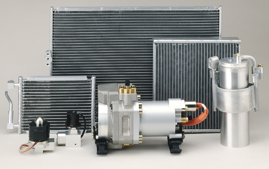
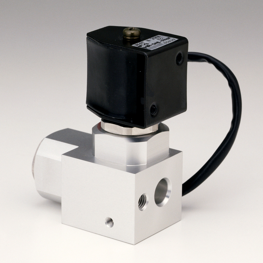
Due to the fact that concerns regarding the effect of global warming have been growing in recent years, the refrigerant of automobile air conditioning systems was switched from CFC-12 to HFC-134a in many countries. Unfortunately, the global warming potential of HFC-134a refrigerant is still high, and therefore air conditioning systems are required to use a more environmentally benign CO2 refrigerant to prevent global warming.
CO2 has a critical temperature lower than that of HFC-134a and a critical pressure higher than that of HFC-134a. Therefore, in air conditioning systems adopting CO2 refrigerant, a high-pressure side temperature exceeds the critical point. This results in a high operation pressure that is 7 to 10 times larger than that of HFC-134a. Figure 11 illustrates the key components of the DENSO CO2 refrigerator (Figure 12). (Photos Courtesy of DENSO Inc., USA, Japan).
INTEGRATED DIGITAL CAR AND DIGITAL FACTORY MODEL APPLICATION CASE: SENSORS AND SOFTWARE SYSTEMS FOR SOLVING DIGITAL CAR STABILITY
In this case we briefly investigate how Sensors and Software Systems for Solving Digital Car Stability could be integrated into our digital factory and digital automobile models, for the purpose of maximizing the benefits of the offered technologies.
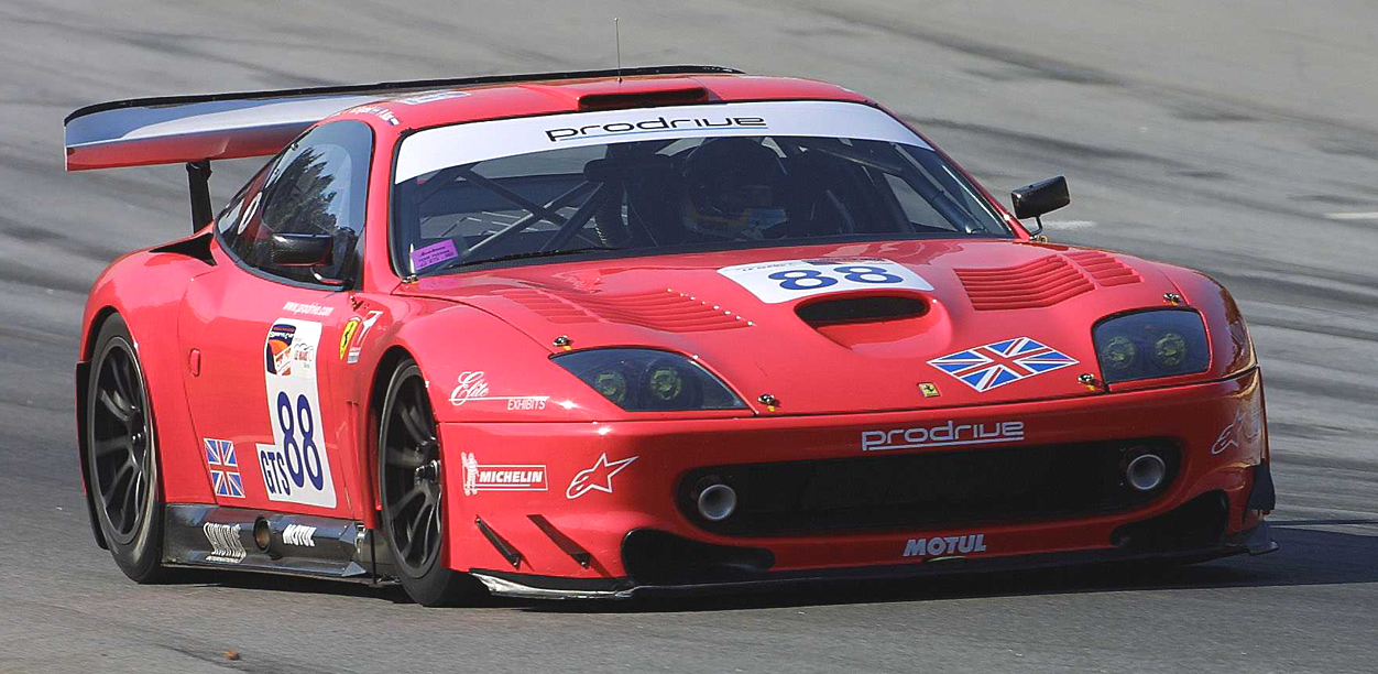
Designed for road car applications in all market sectors, the new system, called Active Torque Dynamics (ATD™), developed by Prodrive modulates the torque distribution to individual wheels to increase the rate at which the vehicle will turn. Prodrive claims this provides a superior performance and feel compared with conventional brake apply systems and can increase driver confidence in emergency situations.
“Road cars are generally driven in the ‘linear region’,” explains Damian Harty Prodrive dynamics specialist. “However, when something unexpected happens, drivers tend to apply more steering angle than the vehicle can actually follow (around 10 degrees at the road wheels) and the vehicle behavior changes significantly. This change is enough to confuse many drivers at a critical moment and can lead to loss of control in emergency situations. ATD™ extends the linear region, making the vehicle much more controllable in emergency situations.”
ATD™ uses data from wheel speed sensors (which can be shared with the antilock braking system, ABS), a yaw rate sensor and a steering wheel angle sensor to compare what the driver is requesting with what the vehicle is providing. If the driver is accelerating, or has some throttle applied, a torque can be applied to the appropriate wheel to counter oversteer or understeer. If the driver is braking, or there is zero throttle signal and the system is integrated with a conventional stability program, it can brake the opposite wheel to enhance directional stability while reducing vehicle energy.
Figure 13 illustrates the Active Torque Dynamics (ATD™) system, developed by Prodrive designed for road car applications. (This system modulates the torque distribution to individual wheels to increase the rate at which the vehicle will turn. Photograph courtesy of Prodrive, UK).
The new system works using active center, front and rear differentials by locking or releasing them to dynamically modulate the torque applied to each wheel. Prodrive has developed a number of control strategies to ensure that torque distribution is suited to each stage of different manoeuvres and that the system can be applied equally effectively to different types of vehicle.
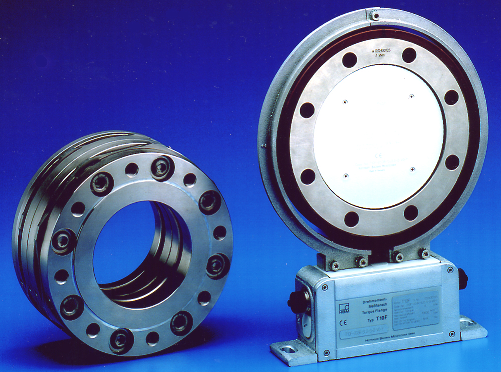
Figure 14: The T10F Torque Flange. (Photo courtesy of HBM, Inc. USA).
The illustrated T10F Torque Flange amplifier enables easy linking to numerous interfaces in the networked, digital garage, including fieldbus systems, RS232/485, Printerport, IEEE 488, Ethernet TCP/IP, Interbus S, CANopen and Profibus DP.
As it can be seen in our digital car and factory models, currently under research, we see the above challenge to be placed following an integrated, analytical, quantitative and computational approach in our digital factory/ car models (Figure 10).
INTEGRATED DIGITAL AUTOMOBILE AND DIGITAL FACTORY MODEL APPLICATION CASE: ON-BOARD NETWORKING CHALLENGES, AS WELL AS COMMUNICATIONS SOLUTIONS WITH EXTERNAL NETWORKS
In this case we briefly investigate how On-board Networking Challenges, as well as Communications Solutions with External Networks could be integrated into our digital factory and digital automobile models, for the purpose of maximizing the benefits of the offered technologies.
The Internet is changing everybody’s life, and the digital, networked automobile is no exception. It is becoming an increasingly “intelligent” node in a TCP/IP network. Computer networking hardware and software companies don’t claim to be experts in engine design, or consumer oil-change habits and mistakes, or what to do if the tires are flat, nevertheless can make digital cars “talk” to consumers, maintenance experts and others over Internet networks and scale interoperable software systems that work in smart sensors, up to engine management computers, networked via gateways and routers, using wireless technologies to garage computers and digital home networks.
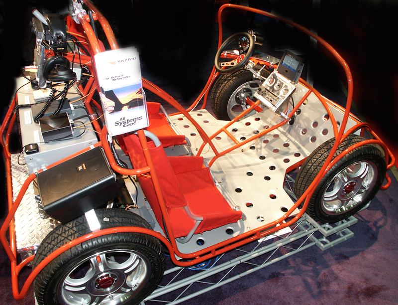
To illustrate this case, Figure 15 is the Yazaki in-vehicle digital, fiber optic network demonstrator, featuring a Multimedia Vehicle Portal (MVP), GPS (Global Positioning System), a driver navigation system, a vehicle auto gateway for the purpose of integrating multiple wireless and consumer networks, and DVD video and digital audio entertainment systems. (Photo courtesy of www.cimwareukandusa.com)
In terms of OEM and dealer applications, the opportunities thought of by IBM, Microsoft, GenRad, Sun Microsystems, using the Java platform, and other major vendors, are wide open too. Some ideas, backed by real-world automobile demonstrators include the following:
- Remote monitoring of wear items (e.g. engine oil life, tire pressure, unwanted noises, vibrations) combined with personalized driver alerts, allowing manufacturers to remind owners/ operators of vehicle maintenance requirements, that in return reduce warranty costs, can increase trust in a particular brand garage, and give opportunities for targeted service sales through service partners,
- Automatic software updates via the telematics capabilities of the car, and its computing systems without visiting a service station,
- Collection and aggregation of operational data from vehicles by geographic area, operating point and mileage allowing for rapid statistical analysis of problems, recall decisions, future design decisions, quality issues, and many others,
- Technical updates and recall notes can be emailed to the digital car’s automatically, with return acknowledgement, augmented with service appointment reminders and scheduling.
Further application areas include electronic support systems for highway toll collection, vehicle theft protection (using voice control ID systems, that are extremely difficult to break and /or mimic), purchase and automated download of MP3 digital music and DVD video entertainment at petrol stations.
A NETWORK SIMULATION EXAMPLE USING THE OPNET Modeling METHOD AND SOFTWARE TOOL
The goal of most simulation scenarios is to evaluate some aspect of a system’s behavior or performance, and to quantify, typically in terms of statistics, the results, and then use the results for decisions. This requires a simulation environment with software tools that provide insight into a model’s dynamic operation.
To follow a safe, systematic, analytical, quantitative, and cost effective approach, design engineering teams should put significant effort into simulating various networked scenarios, with a variety of different protocol stacks, to come to the best solutions, when evaluating functionalities as listed above.
Figure 1 illustrates the basic collaborative activities of two simplified ‘digital factories’, using dataflow diagrams, as the modeling tool. By studying the key processes (modeled as ellipses) and the interactions/ data flows between the processes and the data stores (modeled as two parallel lines), and the data sources and sinks (modeled as boxes), one can follow the value chain along the processes and make the collaborating organizations leaner and eventually minimize waste.
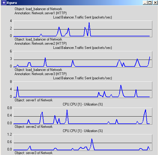
Figure 16 illustrates a networked system simulation screen in IT-GURU (by OPNET Technologies, USA). This simulation model has been configured in such a way, that it utilizes three servers linked to a balancing computer (these could be part of the digital factory hub), linking to the digital car wireless networks (clients in our model) via the Internet. As we can see from the results, we are simulating the unfortunate case, when one, server _3, of the otherwise well balanced servers breaks down at 5 minutes into the simulation, and then gets repaired, and recovers 30 minutes later.
Based on IT-Guru’s in-depth analysis, the network engineering analyst can collect object, scenario-wide and global statistics as follows:
- Object statistics are collected from individual objects. They allow the network engineering analyst to evaluate the performance of specific network nodes or links (a single hub’s Ethernet delay, or a server balancing change, due to a repairable fault, as in our example).
- Scenario-wide object statistics are collected from all relevant objects in a network (for example, Ethernet delay for every node, a node being a digital car, or a workstation in a digital factory). They allow the network engineering analyst to easily monitor the performance of all objects of a specific type. (Note, that, this can be mission critical, if the particular objects are related to automobile safety, or security).
- Global statistics are collected from the entire network. They represent results that apply to the network as a whole (such as global end-to-end delay) and let the designers and management analyze aspects of the network’s overall performance, and therefore make well researched, and wise decisions.
More specifically, IT-Guru offers the following types of statistics, when analyzing networks, including options for a digital car (as a client) and the digital factory (as the server) networks:
- Queue Size
- Available Space
- Overflow Occurrences
- Delay
- Inter-Arrival Times
- Packet Sizes
- Throughput
- Utilization
- Error Rates
- Collisions, and
- Application-Specific Statistics defined by the model developer.
Because there are many possible statistics to collect, the data files would quickly grow past practical use if the simulation program recorded them all. Therefore, the analyst must specifically select the statistics that is valuable for the particular study to collect before running a simulation (IT-Guru, OPNET Technologies, 2002, Ranky, P.G., 2002a, 2002c). As in our simplified example, as illustrated in Figures 1 and 2, based on the plotted graphs and screens, management can easily evaluate the need of the balanced server architecture, and even investigate ‘what if’ scenarios further, without committing themselves to major upfront investments
As stated earlier, this is just the beginning. As in the case of a modern factory, in which every major machine / process is a web-page, as soon as the automobile becomes digital the opportunities of hands free, wireless, voice controlled devices will populate our lives; and hopefully give pleasure and yield a more satisfied consumer than before. (Ranky, 2002a, 2002b, Rappl, 2002, Rushton, 2002, Sporton, 2002, Wendorff, 2002, and Ranky, 2003).
Certainly the challenge is here, and the opportunities for creating new exciting product is great. It is now up to us, the automotive design, manufacturing, IT, maintenance, marketing, engineering management, and education community to try to satisfy our customers better, and simultaneously enjoy the process…
Summary
Jump to top
Due to market pressures, within 10 years the automobile industry will have to produce a brand new automobile within 24 months; and within 20 years this will shrink to just over 12 months, or probably even less, due to the application of re-usable objects and components (both physical, as well as software).
As a conclusion, the digital , telematic –enabled and integrated, networked automobile, the related electronic support systems, as well as at the design stage in the digital factory, have to rely on fail-safe sensor-to-software components and integration. The “no problem, just reboot” practice dominated by some leading software companies, and the disappointing fact, that 75% of software projects fail today, will not survive in safety-critical/ real-time environments (even if the marketing is force full, dominating, or excellent). Furthermore, none of us want another wave of VCR or mobile phone programming challenges, that are only complex because the user interface/ software designers didn’t care about what the consumers really needed, or ever wanted…
Therefore the message is not new, and very simple: in order to understand, and then control, for the benefit of the users, customers and the entire business of the digital automobile with a future, we need to model our factories and cars, using robust analytical, quantitative, and computational methods, because this is a well
proven engineering approach to solving complex problems.
Furthermore, our marketing, design and manufacturing / assembly / quality control and software engineers and managers should focus on finding out what the customers (and the cars) really need and want, and then implement them in such a way, that drivers and passengers can customize the offered simple as well as complex features in an EASY way. (Again, simple and EASY way…). In this sense, the digital car should become part of the digital home, and the ‘digital hub’, as well as the digital factory, where it was conceived, within this object-linked, distributed and networked system.
Last but no least, the message to the automotive design, manufacturing and education community is clear: integrate disciplines, don’t treat the world as isolated islands of pockets of knowledge… everything relates to everything in our complex knowledge-age, therefore we need to model systems, and then select/ develop skills, resources and new knowledge to tackle the challenges concurrently
References and further reading
Jump to top
Abdu, H.M. and Yoon, D.H. (2002),”The Application of Middleware to In-Vehicle Applications”, Proceedings of SAE 2002 World Congress, Detroit, Michigan, March.
Ashton, P.H., and Ranky, P.G. (1998), “Automotive Design and Assembly System Modeling Research Toolset at Rolls-Royce Motor Cars Ltd.”, Assembly Automation, MCB University Press, Vol. 18, No. 2, 1998 2nd issue, pp.138-152.
Coelingh, E., Chaumette, P., Andersson, M. (2002),”Open-Interface definitions for Automotive Systems. Application of a Brake by Wire System”, Proceedings of SAE 2002 World Congress, Detroit, Michigan, March.
Culp, C.T. (2002),”Predicting the Image Stability Rating for an Automotive Side View Mirror System”, Proceedings of SAE 2002 World Congress, Detroit, Michigan, March.
Dilich, M.A., Kopernik, D. and Goebelbecker, J. (2002),”Evaluating Driver Response to a Sudden Emergency: Issues of Expectancy, Emotional Arousal and Uncertainty”, Proceedings of SAE 2002 World Congress, Detroit, Michigan, March.
Gautschi, G. and Mandel, B. (1998) Sensors and Tools In Engine and Vehicle Engineering, ATZ/ MTZ- Sonderausgabe, Kistler, 1998.
Harrison, M.E. (2002),”A New Generation of High-Pressure Sensor for Common-Rail Systems”, Proceedings of SAE 2002 World Congress, Detroit, Michigan, March.
Ihara, Y. (2002),”Human Machine Interface Design for Driver Information Systems”, Proceedings of SAE 2002 World Congress, Detroit, Michigan, March.
Jackson L.D., and Bhise V.D. (2002),”An Evaluation of the IVIS-Demand driver Attention Demand Model”, Proceedings of SAE 2002 World Congress, Detroit, Michigan, March.
Johannessen, P., Ahlstrom K., and Torin J. (2002),”Conceptual design of Distributed by-wire Systems”, Proceedings of SAE 2002 World Congress, Detroit, Michigan, March.
Karimi, G., Chan, E.C., Culham, J.R., Linjacki, I. And Brennan, L. (2002),”Thermal Comfort Analysis of an Automobile Driver with Heated and Ventilated Seat”, Proceedings of SAE 2002 World Congress, Detroit, Michigan, March.
Matsunaga, M, Miki Y., Miyata Y., and Tanaka K. (2002),”Usability Evaluation of Integrated Switch Systems”, Proceedings of SAE 2002 World Congress, Detroit, Michigan, March.
Nakae, M. (2002),”The Development of a Planar Air Fuel Ratio Sensor”, Proceedings of SAE 2002 World Congress, Detroit, Michigan, March.
Nasr, K. and AbdulNour, B. (2002),”Temperature Measurement of a Vehicle’s Windshield Using liquid Crystals”, Proceedings of SAE 2002 World Congress, Detroit, Michigan, March.
Ranky, P G, Caudill, R. J., Limaye K., Alli, N., Satishkumar ChamyVelumani, Apoorva Bhatia and Manasi Lonkar A.A. (2002),” Web-enabled Virtual Disassembly Manager (webVDM) for Electronic Product / Process Designers, Disassembly Line Managers and Operators”, IEEE International Design For Environment Conference, San Francisco, May 2002 (in the Proceedings) Accepted Paper.
Ranky, P G, Caudill, R. J., Limaye K., Alli, N., Satishkumar ChamyVelumani, Apoorva Bhatia and Manasi Lonkar A A. (2002), “Disassembly User Requirements Analysis Method and Validated Examples”, IEEE International Design For Environment Conference, San Francisco, May 2002 (in the Proceedings) Accepted Paper.
Ranky, P. G. (1997), “An Object Oriented Electronic Enterprise Modeling & Design Method with Rolls-Royce and Small Manufacturing Enterprise Examples”, Norfolk, VI, USA, October 23-26, 1997, American Society for Engineeing Management, National Conference, Proceedings, p. 499-508
Ranky, P. G. (2000),”Some Analytical Considerations of Engineering Multimedia System Design within an Object Oriented Architecture”, IJCIM (International Journal of CIM), Taylor & Francis, London, New York, Vol. 13, No. 2, May 2000, p. 204-214
Ranky, P. G., and Ranky, M. F. (1997), “Engineering Multimedia CD-ROMs with Internet Support for Educating the Next Generation of Engineers for Emerging Technologies”, ETFA ‘97, The 6th International IEEE Conference on Emerging Technologies and Factory Automation, Los Angeles, USA, September 9-12, 1997. Proceedings p.76-81.
Ranky, P.G. (2002a), “A 3D Multimedia Case: Component Oriented Disassembly Failure Risk Analysis, An interactive multimedia eBook publication with 3D objects, text and videos, and active code in a browser readable format on CD-ROM/ intranet by http://www.cimwareukandusa.com”, CIMware USA, Inc. and CIMware Ltd., UK, ISBN 1-872631-47-9, 2001-2002.
Ranky, P.G. (2002b), “A 3D Multimedia Case: Component Oriented Disassembly User Requirements Analysis, An interactive multimedia publication with 3D objects, text and videos in a browser readable eBook format with active code, on CD-ROM/ intranet by http://www.cimwareukandusa.com”, CIMware USA, Inc. and CIMware Ltd., UK, ISBN 1-872631-50-9, 2001-2002.
Ranky, P.G. (2000), “Engineering Multimedia in CIM (Computer Integrated Manufacturing), IJCIM, International Journal of CIM, Taylor & Francis, London, New York, Vol. 13, No. 2, May 2000, p. 169-171
Ranky, P.G. and Tricamo, S. (1998), “Smart Dart: A Smart Diagnostic and Repair Tool”, Assembly Automation, Bedford University Press, Vol. 18, No. 2, 1998 2nd issue, pp.166-167.
Ranky, P.G., and Ranky, M.F. (1997), “Interactive Multimedia for Engineering Management Education and Distance/ Open Learning”, Norfolk, VI, USA, October 23-26, 1997, American Society for Engineering Management, National Conference, Proceedings, p. 49-59
Rappl, M., Braun, P. Beeck, M. von der., and Schroder, C. (2002),”Automotive Software Development: A Model based Approach”, Proceedings of SAE 2002 World Congress, Detroit, Michigan, March.
Rushton, G., Zakarian, A. and Grigoryan T. (2002),”Algorithms and Software for the Development of Modular Vehicle Architectures”, Proceedings of SAE 2002 World Congress, Detroit, Michigan, March.
Sporton, M. (2002),”The UK Foresight Vehicle Programme”, Proceedings of SAE 2002 World Congress, Detroit, Michigan, March.
Wendorff, W von. (2002),” Communication is the Base of tomorrow’s Highly Reliable Automotive Electronics”, Proceedings of SAE 2002 World Congress, Detroit, Michigan, March.
Ranky, P. G. (2003), “An Introduction to Digital Factory and Digital / Telematic Car Modeling with R&D, and Industrial Case Studies”, An interactive multimedia eBook publication with 3D objects, text and videos, and active code in a browser readable format on CD-ROM/ intranet by http://www.cimwareukandusa.com, CIMware USA, Inc. and CIMware Ltd., UK, ISBN 1-872631-66-5, 2003.
Web resources: http://www.gridwatch.com